We have discovered that this objective, and other useful benefits, can be obtained when the reflectivity of the composite pattern is measured at wavelengths complementary to the colors of the first and second patterns.
This method is inconvenient in having to remove a sample of printed substrate from the printer and to interpose a selected filter, the light output of most
white light sources is unpredictable over time, both in terms of power and
wavelength distribution. The known device requires
moving parts to enable filters to be changed, or the use of a number of separate detectors. Filters reduce the light reflectivity reaching the detectors, resulting in the need for higher
exposure times or more sensitive detectors than would otherwise be the case.
Light emitting diodes (LEDs) are readily available, have a short warm-up time, have a longer life and are more reliable in terms of energy and
wavelength band output than conventional
white light sources. By using light sources of a given
wavelength band output, the need for filters is avoided. LEDs are also very low in cost, with the result that the reflectometer can be manufactured for a cost which is orders of magnitude cheaper than conventional devices.
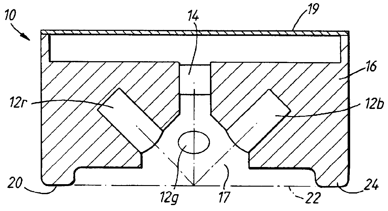
In one embodiment, the LEDs and the
detector are mounted in a common housing. The mounting of the LED
assembly and the
detector in a common housing has the
advantage that the
angle of incidence of light from the LEDs on the printed material
lying in the
measurement plane, remains constant. This angle is preferably close to 45.degree., such as from 40.degree. to 50.degree.. The angle of reflection of light from the printed material
lying in the
measurement plane to the
detector is preferably about 90.degree., such as from 80.degree. to 100.degree.. The housing preferably defines an aperture, behind which the LEDs and the detector are positioned. The smaller the size of the aperture, the smaller need be the size of the patterns or the higher may be the number of readings which can be taken on a given pattern. A smaller aperture, however, requires LEDs of higher output energy, multiple LEDs per
wavelength band or a detector of higher sensitivity. As a consequence, smaller test pages can be generated which results in less waste. Also continuous measurements become more cost efficient. In any event, the aperture should be wider than the sum of the width of a registration marks and an adjacent space in the measurement direction.
Since no
optics are used, the
light intensity detected by the detector depends not only upon the density of the printed substrate but also on the distance thereof from the detector. It is therefore important to position the detector at a fixed distance from the printed substrate. The reflectometer may therefore further comprise means to define a measuring plane in a
fixed position relative to the LEDs and the detector. Where the LEDs and the detector are mounted in a common housing, the housing may have surface portions defining the measuring plane. During measurement, these surface portions lie against the printed substrate, thereby ensuring that the distance between the printed substrate and the detector remains constant. The surface portions are preferably formed of a
low friction material. This enables the monitoring to be carried out while the printed substrate is moving relative to the reflectometer, without causing damage to the printed substrate. In an alternative embodiment, the housing of the device includes a roller in rolling contact with the substrate close to the measuring position to ensure that the LEDs and the detector remain at a fixed distance from the printed substrate. While it is possible to construct the reflectometer to move in
synchronism with the printed substrate, this requires a more complicated construction and
control system and is therefore less preferred.
In order to ensure that the detector is positioned correctly to make the required measurements, a calibration of its position relative to the edge of the substrate is recommended. Means are therefore preferably provided for
lateral movement of the device. To ease the location of the reflectometer directly above the composite patterns, where the substrate is in the form of a web, the device may be mounted on a track extending across the web path, with a motor provided to drive the device along the track. This can be particularly beneficial if the printer includes a web alignment compensation
system in which variations in web alignment are detected and compensated for by lateral adjustment of the image forming
system, or where the printer is to be used for a number of different types of output in which patterns are located in different lateral positions. The means for enabling
lateral movement of the device may enable the device to be "parked" in a covered zone away from the web, to facilitate
web handling.

