Structures of optical fiber cables self-reinforced against compression

a technology of optical fiber cables and structures, applied in the field of reinforcement structures, can solve the problems of twisted cables on curved paths with small radius, high rigidity of known cables, and low rigidity of structures designed to withstand

Inactive Publication Date: 2000-05-23
HANGER SOLUTIONS LLC
View PDF10 Cites 39 Cited by
  • Summary
  • Abstract
  • Description
  • Claims
  • Application Information

AI Technical Summary

Problems solved by technology

The known cables have the drawback of high rigidity related to the structures designed to withstand compressive and tensile strains.
Another drawback specific to cable structures in ribbon form is that they get twisted on curved paths with small radius.
Such drawbacks rule out domestic applications as domestic cables have to withstand specific mechanical strains due to the low radii of curvature in the boxes, internal wiring systems, thermal shock and overhead wiring with elongation.

Method used


Image

  • Structures of optical fiber cables self-reinforced against compression
  • Structures of optical fiber cables self-reinforced against compression
  • Structures of optical fiber cables self-reinforced against compression

Examples


first embodiment

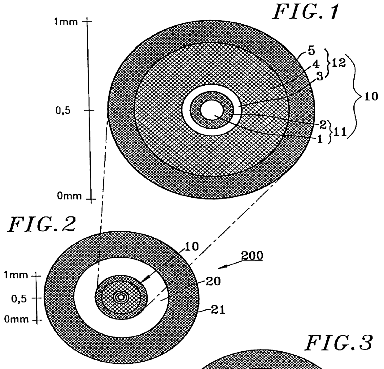
The monofiber cable 200, according to this first embodiment, comprises a single axial optical module 10, having the constitution explained here above with reference to FIG. 1. The optical module 10 is coated directly with fiber wicks forming a tubular flexible reinforcement module 20 according to the invention. The modules 10, 20 are finally molded in an external sheath 21.

According to a first non-restrictive exemplary embodiment, the tubular reinforcement module 20 has an internal diameter of 1.2 mm and an external diameter of 2.2 mm, the thickness of the microfiber wicks being then 0.5 mm. The external sheath 21, in this first example, has a thickness of 0.7 mm, giving a final cable diameter of 3.6 mm. Thus, a monofiber cable 200 is obtained with a yield strength of over 500 N measured for an elongation of 0.3%.

In a second exemplary embodiment of a monofiber cable 200, the tubular reinforcement module 20 has an internal diameter of 1.2 mm and an external diameter of 2 mm, the wick...

second embodiment

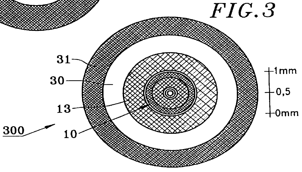
FIG. 3 shows a second embodiment in which a monofiber concentric cable structure 300 closely resembling the cable 200 is adopted.

Unlike the first embodiment, an intermediate tubing 13 is planned, according to the invention, between the axial optical module 10 and the peripheral reinforcement module 30, external sheath 31 similar to sheath 21 of FIG. 2. The tube 13 is formed by a plastic material chosen especially from among the polymers such as charged polyvinyl chlorides and polyolefines. The plastic material is preferably a flame-retardant material made, for example, by being treated with aluminum hydrate or any other fire-retardant material without any halogenide (chloride, fluoride or bromide) to prevent toxic discharges.

The plastic tube 13 has a wall thickness of about 0.5 mm. The tube 13 for example has an external diameter of 1.3 mm and an external diameter of 2.3 mm as shown in FIG. 3.

One advantage of the second embodiment is the excellent compressive strength and shear stre...

third embodiment

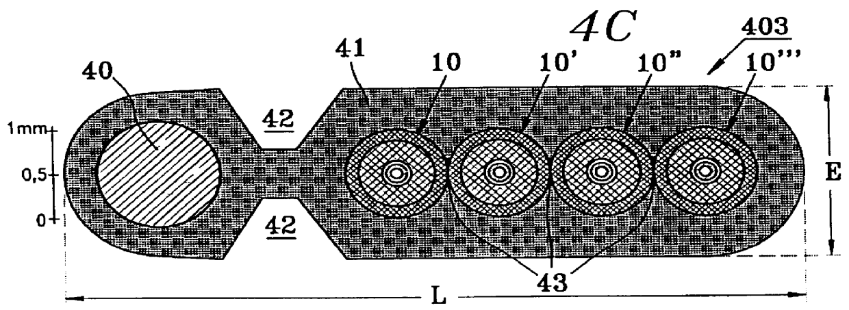
FIG. 4 shows a cable in which the modules have substantially coplanar axes.

According to the invention, a single flexible reinforcement module 40 with a cylindrical shape is positioned laterally and with a spacing in relation to associated optical modules.

FIG. 4A thus shows a monofiber cable 401 comprising a reinforcement module 40 and an optical module 10 molded in the external sheath 41. The module 40 and the module 10 are spaced out and the molding of the sheath has one or two longitudinal grooves 42 that are hollowed out along the median axis of spacing of the modules 10 and 40. An arrangement of this kind enables the easy separation of the optical module 10 and the reinforcement module 40 in domestic connections. Another advantage of such an arrangement is that, on an overhead portion, the cable 401 may be fixed by placing a tight clamp to the lateral reinforcement module 40 without damaging the optical module.

The groove 42 however is optional, for the sheath may have a full sec...


PUM


Abstract

A modular optical transmission cable which has several reinforcement and optical modules, each optical module having: a sheathed optical fiber, coated with: an intermediate decoupling layer, and with a rigid shell forming a microcarrier, a reinforcement module being associated with an optical module, the modules being molded in an external sheath. A flexible reinforcement module is associated with at least one optical module that is self-reinforced against compression in order to obtain a cable having high flexibility combined with high compressive strength. The disclosure can be applied in the field of optical fiber cables and especially that of the reinforcement structures of such cables and fibers.

Description

1. Field of the InventionThe present invention relates to the field of optical fiber cables and especially to the reinforcement structures of such cables and fibers.Optical fibers used for telecommunications by optical signals are elements based on silicates (glass or quartz) that are particularly brittle and poorly withstand weight, tensile and compressive forces. There are known ways of using reinforcement structures to form an optical fiber cable designed to cover long-haul and short-haul communications.2. Description of the Prior ArtThe patent FR-A-2 728 694 filed on behalf of the present Applicant teaches an elementary reinforcement structure in which at least one optical fiber is inserted into a rigid shell called a microcarrier to form an optical module (also called a micromodule) that is reinforced in order to limit the curvature of the fiber and the attenuation of the optical signals.The patent application No. FR-A 2 747 201 filed on behalf of the present Applicant teaches ...

Claims


Application Information

Patent Timeline
Patent Type & Authority Patents(United States)
IPC IPC(8): G02B6/44
CPCG02B6/4402G02B6/4432G02B6/0288G02B6/4436G02B6/443
Inventor RUELLO, YVESLOUBOUTIN, JEAN-PIERREMORGAND, ANNIE
Owner HANGER SOLUTIONS LLC
Why Eureka
Try Eureka