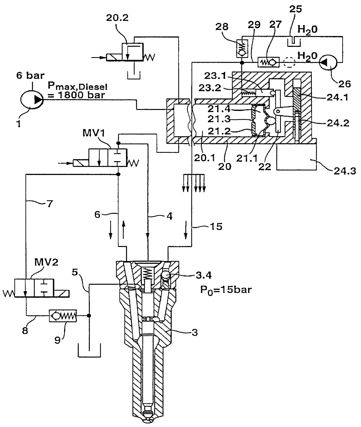
The indirect delivery of additive fluid can take place, for example, by way of a pump
piston which is connected to the membrane by means of a lever mechanism and which, when there are pressure changes in the common
rail pressure reservoir that lead to a membrane movement, delivers a corresponding quantity of additive fluid. In order to compensate for a membrane path drift, for example when there are various common rail basis pressures, as well as in order to precisely regulate the quantity metering of the additive fluid delivered, the lever ratio and therefore the
stroke volume of the pump
piston can be influenced by means of an adjusting mechanism, which can be driven, for example, by means of an
electric motor. Due to the proportionality of the withdrawn fuel quantity to the delivered additive fluid quantity, however, adjustments may hardly be necessary so that the device according to the invention has a high degree of
operational stability.
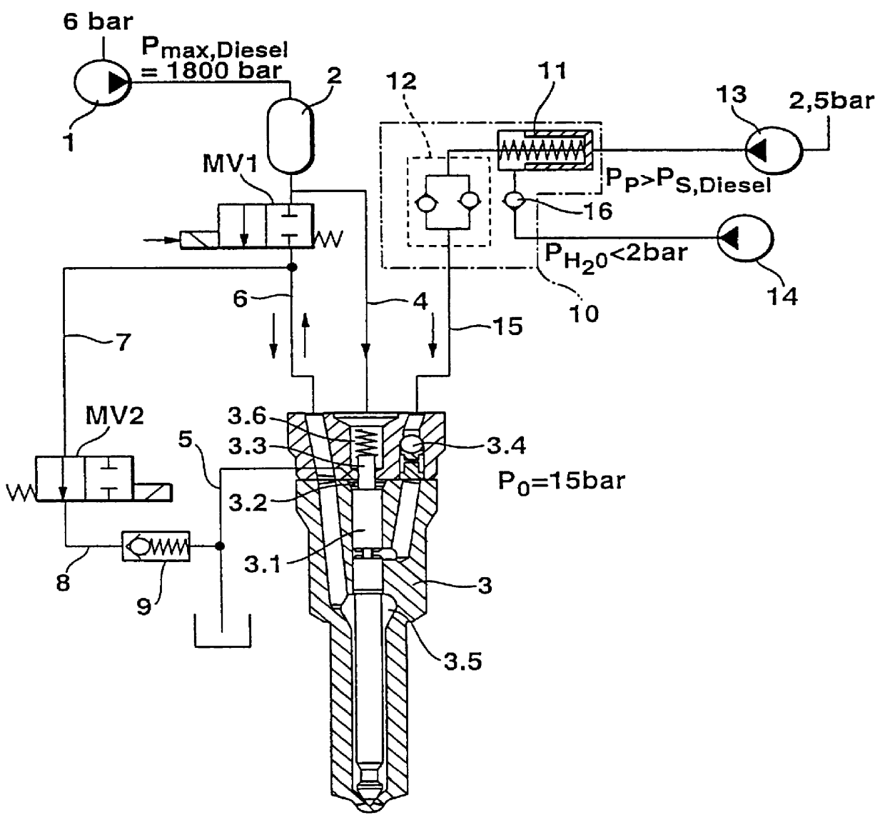
One embodiment of the fuel injection system according to the invention is particularly preferable in which in order to deliver the additive fluid, a membrane is used whose one side is acted on by the
high pressure prevailing in the common
rail pressure reservoir and whose other side, due to the pressure impulses in the common rail pressure reservoir, produces a delivery of additive fluid into the additive fluid line leading to the dual-fuel injector either directly or via a lever mechanism.
In order to simplify the design and thereby reduce the cost of its manufacture, the fuel injection system will be set forth hereinafter. As a result, the two complex and expensive 3 / 2-way solenoid
control valves can be replaced with simpler and less expensive 2 / 2-way valves, which simultaneously raises the possibility of shifting the quantity metering for the additive fluid to a single, precisely operating metering valve that can serve an entire group of injectors. Whereas the second 2 / 2-way valve only controls the opening and closing time for the storing up of additive fluid, the quantity metering for the fuel quantity to be injected is produced by means of a corresponding
time control of the first 2 / 2-way valve in the injection line between the common rail pressure reservoir and the pressure chamber.
In order to assure uniform pressure conditions in the line system and in particular, in order to prevent a degassing of the additive fluid--as a rule water--when the
boiling point is exceeded, even at high temperatures, the use of a
check valve is suggested between the second 2 / 2-way valve and the low-pressure fuel side.
It is also advantageous if, on the blunt end of its injector
tappet, the injector needle supports a small
piston in the radial extension, which piston protrudes into a chamber that is acted on with
high pressure from the common rail pressure reservoir and is in turn sealed off in a pressure-tight manner from the chamber encompassing the injector needle. Through the impingement of the common rail pressure on the uniform piston surface, the control movements of the injector needle in the injection process are independent of the absolute pressure conditions in the common rail pressure reservoir because in order to move the injector
tappet, the same resistance, namely the
spring force of the valve spring, must always be overcome so that the movement forces remain constant. As a result, constant switching times are produced that are favorable for technical regulating reasons and that are determined by the respective movement time of the injector
tappet.
One embodiment of the fuel injection system according to the invention is particularly preferable in which in order to deliver the additive fluid, a membrane is used whose one side is acted on by the
high pressure prevailing in the common rail pressure reservoir and whose other side, due to the pressure impulses in the common rail pressure reservoir, produces a delivery of additive fluid into the additive fluid line leading to the dual-fuel injector either directly or via a lever mechanism.
The indirect delivery of additive fluid can take place, for example, by way of a pump piston which is connected to the membrane by means of a lever mechanism and which, when there are pressure changes in the common rail pressure reservoir that lead to a membrane movement, delivers a corresponding quantity of additive fluid. In order to compensate for a membrane path drift, for example when there are various common rail basis pressures, as well as in order to precisely regulate the quantity metering of the additive fluid delivered, the lever ratio and therefore the
stroke volume of the pump piston can be influenced by means of an adjusting mechanism, which can be driven, for example, by means of an
electric motor. Due to the proportionality of the withdrawn fuel quantity to the delivered additive fluid quantity, however, adjustments may hardly be necessary so that the device according to the invention has a high degree of
operational stability.
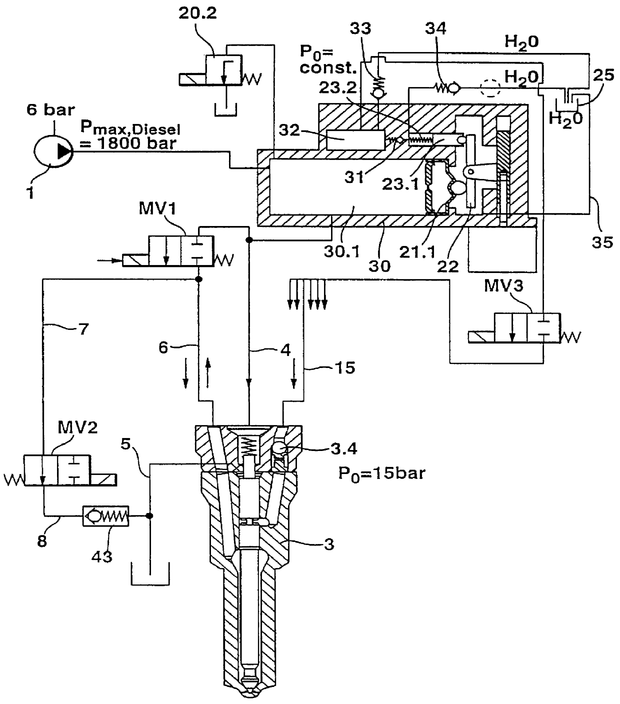
In order to damp smaller pressure fluctuations with higher frequencies, in an improvement, the
delivery system for the additive fluid can be embodied as a type of "hydraulic low-pass filter" in which a
solid dividing wall (also referred to as a
mass wall) clamps the membrane at one end of the common rail pressure reservoir, wherein a diaphragm bore is provided in the
mass wall and permits a damped pressure compensation between the common rail pressure reservoir and the chamber between the
mass wall and the membrane. In the electrical analogy of a low-pass filter, the mass wall would in this connection correspond to the
inductance, the diaphragm bore would correspond to the
ohmic resistance, and the membrane would correspond to a
capacitor. As a result, only larger
low frequency pressure fluctuations due to large volume movements of the fuel affect the membrane movement and therefore the delivery of additive fluid.
An embodiment of the fuel injection system according to the invention is also very particularly preferred in which another common rail pressure reservoir is provided to contain pressurized additive fluid, which is connected by way of a 2 / 2-way valve to additive fluid line leading to the dual-fuel injector and has similar advantages to the intrinsically known common rail pressure reservoir for fuel. In particular, with the use of an additional common rail pressure reservoir of this kind, the above-described delivery mechanism for the additive fluid can be considerably simplified by virtue of the fact that the membrane produces the delivery of additive fluid via a
check valve directly and without the interposition of a lever mechanism, which drives a pump piston,
through transmission of corresponding pressure impacts to the other common rail pressure reservoir.
FIG. 2 shows a second exemplary embodiment with a membrane-operated additive fluid pump, wherein the membrane is controlled by the pressure in the common rail pressure chamber and drives a delivery pump piston by way of a lever mechanism;
Other advantages and advantageous embodiments of the subject of the invention can be inferred from the description, the drawings, and the claims.

