Cylindrical roller stent crimper apparatus with radiation shield

a technology of crimper and cylindrical roller, which is applied in the direction of prosthesis, manufacturing tools, blood vessels, etc., can solve the problems of stent and/or balloon catheter damage, stent reclosure or restnosis, and insufficient performance of these tools

Inactive Publication Date: 2000-06-13
ISOSTENT
View PDF2 Cites 126 Cited by
  • Summary
  • Abstract
  • Description
  • Claims
  • Application Information

AI Technical Summary

Benefits of technology

One other aspect of the present invention provides a shielded stent crimping assembly for loading a radioactive stent onto a deployment device. This assembly includes a crimping mechanism adapted to crimp the radioactive stent onto the deployment device. A shielded crimper body de

Problems solved by technology

Problems occur, however, when the dilatation of the occlusion forms fissures, flaps and/or dissections which may ultimately cause reclosure or restenosis of the vessel.
The performance of these tools, however, is not completely satisfactory since there is still a wide divergence between application force, profile and stent diameter.
Problems arise when excessive crimping forces are applied to the crimp pliers which can damage the stent and/or balloon catheter.
This is especially problemsome given the minute size of the stents which are typically on the order of about one (1) mm to four (4) mm in diameter before crimping.
Moreover, non-uniformity of the crimping may be experienced as well as the inability to determine when a reliable and uniform crimp has been achieved.
Thus

Method used


Image

  • Cylindrical roller stent crimper apparatus with radiation shield
  • Cylindrical roller stent crimper apparatus with radiation shield
  • Cylindrical roller stent crimper apparatus with radiation shield

Examples


second embodiment

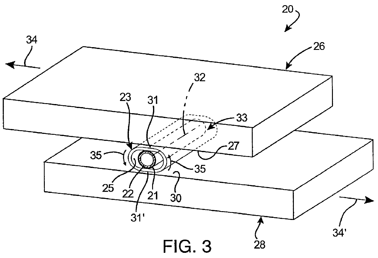
Referring now to FIGS. 4-5C, the stent loading apparatus 20 of the present invention is illustrated for loading a deformable stent 21 onto a deployment device 22. In this embodiment, the first member 26 is provided a crimper body, generally designated 36, having a curvilinear first compression region, preferably wall 27, defining a bore portion 37; and a spindle member 38 having a curvilinear second compression region, preferably wall 30, extending into the bore portion 37 adjacent the first compression wall 27. Collectively, these opposed first and second compression walls define an annular gap 40 between the rotating components where the crimp is to be performed. The spindle member 38 is rotatably coupled to the crimper body 36 for relative rotation of the first compression wall 27 and the second compression wall 30 between a first position (FIGS. 4 and 5A) and a second position (FIGS. 5B and 5C). In the first position, the first compression wall 27 and the second compression wall...

first embodiment

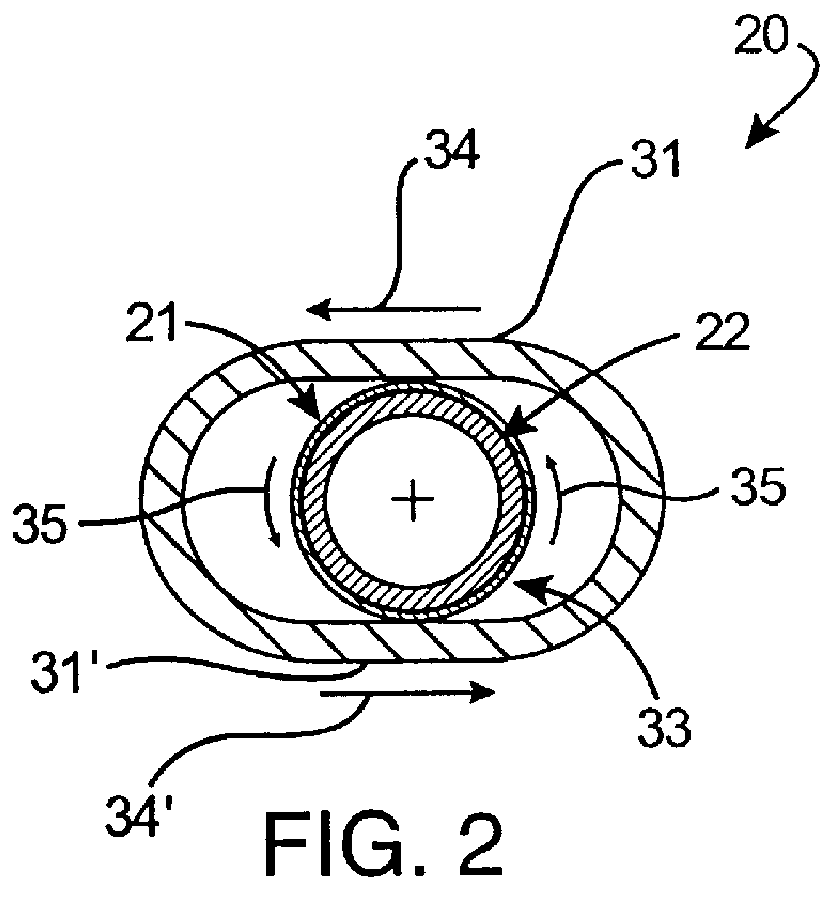
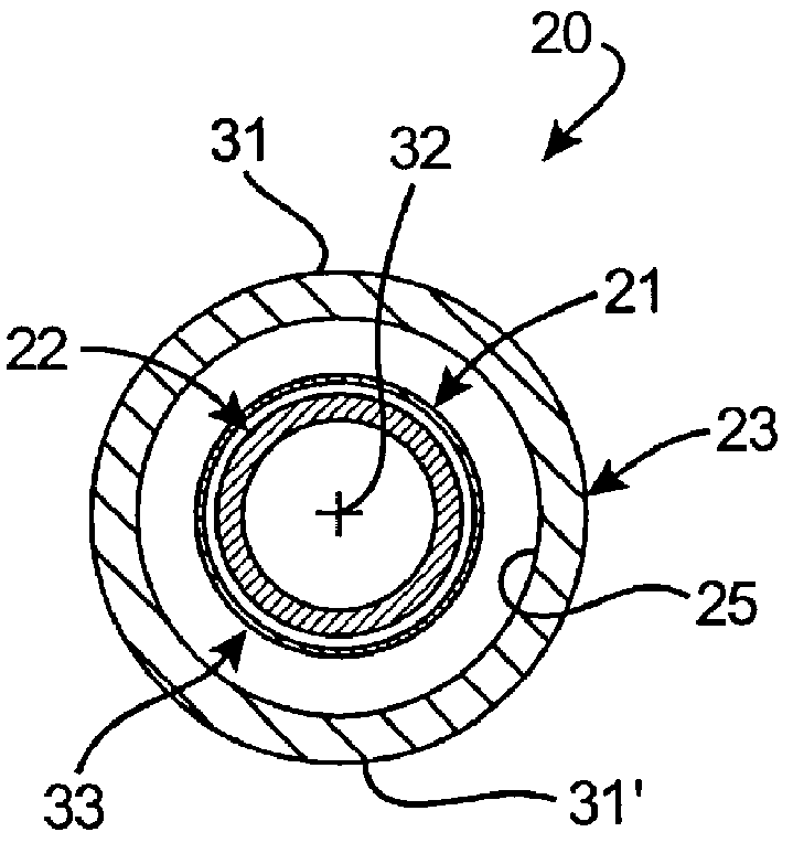
Accordingly, the stent 21 is caused to be radially compressed and simultaneously rolled about its longitudinal axis during the relative rotational movement between first compression wall 27 and second compression wall 30. Analogous to the first embodiment, the first member is provided by the crimper body 36 defining the first compression wall 27, while the second member is provided by the spindle member 38. During relative rotational movement between the crimper body 36 and the spindle member 38, the substantially cylindrical first compression wall 27 rotates relative the cylindrical second compression wall 30 in a manner compressing and rotating the elastic tube 23 therebetween from the first position (FIGS. 4 and 5A) to the second position (FIGS. 5B and 5C) to compressively crimp the stent assembly 33.

Briefly, while the application of the present invention is primarily described and illustrated in connection with the elastic tube embodiment, it will be appreciated that this tube m...

fourth embodiment

Turning now to FIGS. 9-11B, the stent loading of the present invention is illustrated having a planetary gear assembly, generally designated 68, which enables smooth and accurate rotation of the spindle member 38 relative the crimper body 36. This gear assembly 68 further facilitates rolling transport of the stent assembly, the catheter, the crimp tube and the radiation shield about the annular gap 40 at a substantially similar rate and distance, and in a longitudinal orientation between the first and second compression walls.

As shown in FIGS. 11A and 11B gear assembly 68 is configured to cooperate with the crimper body 36, the spindle member 38 and the deployment device 22 to provide rolling support for the stent assembly 33 between the first position (FIGS. 9, 10A and 11A) and the second position (FIGS. 10B and 11B). The planetary gear assembly 68 preferably includes a drive gear 70 fixedly coupled to the proximal end of crimp roller 28 through post portion 71. Positioned circumfe...


PUM

PropertyMeasurementUnit
Diameteraaaaaaaaaa
Elasticityaaaaaaaaaa

Abstract

A stent loading apparatus for loading a deformable stent onto a deployment device. The stent loading apparatus includes an elastic member defining a passage therein formed for longitudinal receipt of the deformable stent in an uncrimped condition. A first member includes a first compression region; and a second member includes a second compression region positioned substantially adjacent the first compression region at a first position. At this first position, the elastic member and the deformable stent in the uncrimped condition may be received between the opposed first and second compression regions. The first compression region and the second compression region are further configured to provide rolling support and compression of the elastic member during relative movement between the first position and a second position for rolling radial compression of the deformable stent onto the deployment device.

Description

The present invention relates, generally, to intravascular stents and, more particularly, to stent crimping apparatus with radiation shields for radioactive stents.Percutaneous Transluminal Angioplasty (PTA) is a medical procedure for widening a stenosis or constriction of a bodily passage. The most common application is to widen the passage of a blood vessel, such as an artery, which has been constricted by the build-up of cholesterol fats or atherosclerotic plaque. When this medical procedure is applied to a coronary artery, it is referred to as Percutaneous Transluminal Coronary Angioplasty (PTCA).Typically, a tip mounted balloon of a balloon catheter is advanced over a guidewire to the stenosis. Once the balloon catheter is properly position, the balloon is inflated to compress the plaque against the vessel walls and widen the stenosis. Problems occur, however, when the dilatation of the occlusion forms fissures, flaps and / or dissections which may ultimately cause reclosure or r...

Claims


Application Information

Patent Timeline
IPC IPC(8): A61F2/06A61F2/84
CPCA61F2/958Y10T29/53657A61F2002/9522A61F2/9522
Inventor DINH, MINH Q.TURNLUND, TODD H.CAMPBELL, THOMAS H.
Owner ISOSTENT
Why Eureka
Try Eureka