Vision based precision docking of vehicles

a vision-based, vehicle-based technology, applied in the direction of navigation instruments, distance measurement, instruments, etc., can solve the problems of insufficient attention to the automation of particular and precise maneuvers, the inability to accurately and accurately align the vehicle relative to a fixed facility, and the wear and damage of the devi

Inactive Publication Date: 2000-06-20
LOCKHEED MARTIN CORP
View PDF7 Cites 66 Cited by
  • Summary
  • Abstract
  • Description
  • Claims
  • Application Information

AI Technical Summary

Problems solved by technology

However, known applications for non-rail vehicle guidance are generally limited to use where exact vehicle position is not particularly critical and the control maintains a particular mode of operation or movement of the vehicle rather than executing a particular maneuver.
However, until recently, the automation of particular and precise maneuvers and the accurate automated positioning of a vehicle relative to some fixed facility (e.g. bus stop, wheelchair access ramp, loading dock, etc.) has not been seriously addressed.
Such devices are subject to substantial wear and damage unless they are buried and buried devices are subject to electromagnetic interference (e.g. reinforcing steel in the roadway).
Therefore, neither type of system has proven particularly reliable and maintenance costs are substantial in any event.
In particular, if tracking of such devices is lost, it is extremely difficult to reacquire, during which autonomous guidance of the vehicle will not be possible.
However, sonar-based systems are very limited in range and subject to interference from ambient noise, wind, doppler effects and the like.
Even for highly directional sonar systems, the area covered and the possible sources of noise increase greatly with distance.
Therefore, sonar-based systems are not able to develop high confidence factors for target acquisition or to acquire targets at a range supporting control of change of course or speed at moderate rates.
Ground clearance of buses means a substantial difference in height of a step

Method used


Image

  • Vision based precision docking of vehicles
  • Vision based precision docking of vehicles
  • Vision based precision docking of vehicles

Examples


Embodiment Construction

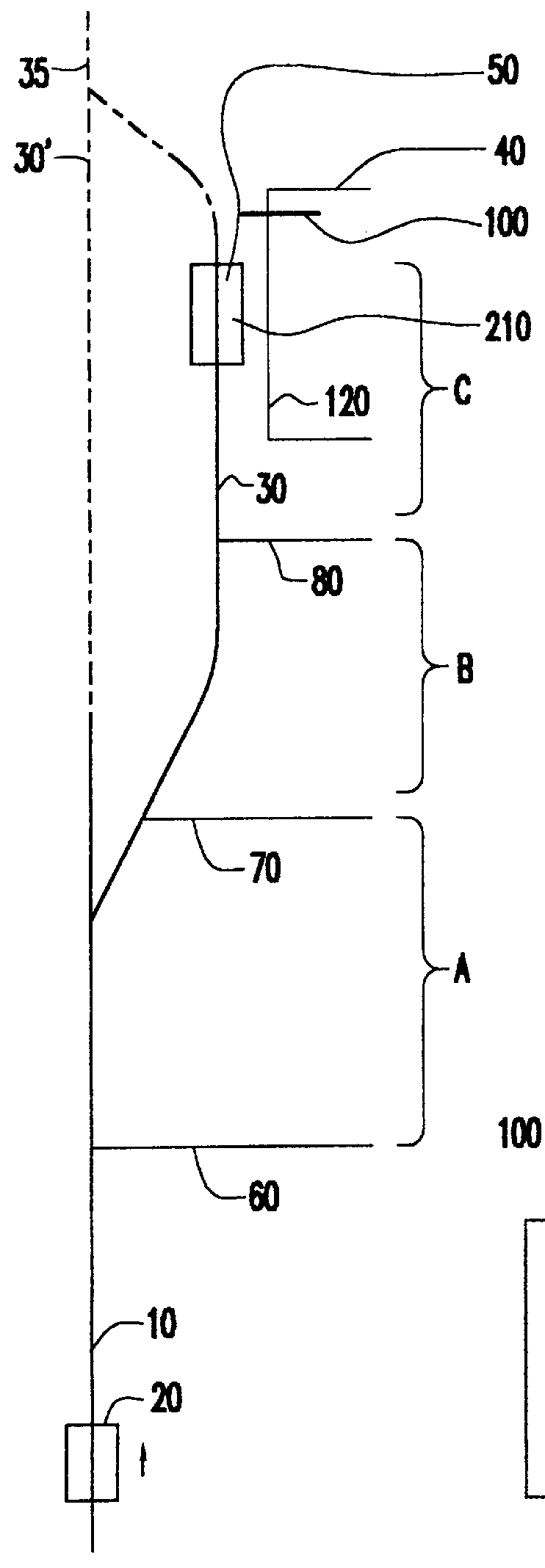
Referring now to the drawings, and more particularly to FIG. 1, there is shown, in plan view, a docking maneuver in accordance with the invention. It should be understood that the initial portion of vehicle path 10 along which vehicle 20 is to travel need not be straight but is so depicted in the interest of clarity. It should be further understood that at the position of vehicle 20 depicted, vehicle 20 could be under manual control or under control of an autonomous guidance arrangement for path following along a highway or other thoroughfare, the details of which are not important to the practice of the invention.

However, in this latter regard, it is preferred that the autonomous guidance system for deriving such a function, if any, also be vision-based, with which the docking system of the invention is particularly compatible and integrable. (It should also be appreciated that the docking system in accordance with the invention is, itself, an autonomous guidance system but the ter...


PUM


Abstract

A three phase control arrangement is employed after visual detection of a target at greater range than otherwise available. The first and last phases employ an optimization criterion for which errors do not vary with distance from a target; limiting the initial error and process error in an intermediate phase which controls approach trajectory to the intended docking location and yielding repeatable high accuracy docking. The three phase approach with different control criteria and control gain parameters makes feasible a docking maneuver that begins at a much greater range and potentially greater lateral separation from the destination than would otherwise be possible, while providing control of both the final location and final orientation of the vehicle. A preferred visual thresholding technique provides consistency of results over a wide range of illumination and contrast conditions while limiting the computation burden for target image acquisition and tracking.

Description

1. Field of the InventionThe present invention generally relates to automatic guidance of vehicles and, more particularly, to the precision execution of docking or parking maneuvers based on visually detectable locations to precisely guide the vehicle to a desired location.2. Description of the Prior ArtVarious approaches have been made to automatic control of numerous aspects of vehicle operation with many differing objectives such as safety, avoidance of operator fatigue and the like which have met with varying degrees of success. For example, for control of automobiles, various arrangements have been proposed to maintain a minimum separation distance between vehicles and regulate speed and / or provide guidance on, for example, high-speed highways. Automatic guidance systems have been employed with substantial success to maintain a chosen course for aircraft and seagoing vessels. For rail traffic, particularly commuter trains in which the vehicle movement is constrained to the locu...

Claims


Application Information

Patent Timeline
IPC IPC(8): B60T7/22G05D1/02
CPCB60T7/22G05D1/0225G05D1/0272G05D1/0255G05D1/0246G05D1/0234
Inventor BRADY, DANIEL G.HOUGEN, DARRELL R.KENNEDY, WILLIAM ASOBETSKI, JEROME F.
Owner LOCKHEED MARTIN CORP
Why Eureka
Try Eureka