Process for the electrolytic deposition of metal layers

a metal layer and electrolysis technology, applied in the field of electrolysis deposition of metal layers, can solve the problems of insufficient establishment of disadvantageous effects, poor and inability to achieve disadvantageous effects, etc., to achieve uniform brightness, improve the distribution of coating thickness, and improve the physical-mechanical properties of deposited metal coatings

Inactive Publication Date: 2000-08-08
ATOTECH DEUT GMBH
View PDF11 Cites 179 Cited by
  • Summary
  • Abstract
  • Description
  • Claims
  • Application Information

AI Technical Summary

Benefits of technology

It has been shown that it is possible to improve the distribution of the coating thickness in deposited metal coatings, particularly in copper coatings, on the surface of complex shaped workpieces and in the borings in the workpieces by means of a pulse current or pulse voltage procedure without thus impairing the physical-mechanical properties of the deposited metal coatings, in particular the uniform brightness and high fracture elongation. When dimensionally stable, insoluble anodes are used for the anodes, the metal distribution on the outsides of the workpiece can also be maintained considerably more uniformly. If the depositing solution finally contains, besides the ions of the deposited metal and the additive compounds for controlling the physical-mechanical properties, also compounds of an electrochemically reversible redox system, by means of whose oxidised form moreover the ions of the deposited metal can be formed by dissolving corresponding metal parts, then flawless coatings can also be obtained optically and in the physical-mechanical properties by using higher current densities (for example over 6 A / dm.sup.2).
In particular, copper coatings with a uniform high brightness can be deposited on circuit boards with fine borings, said copper coatings also having the capacity to withstand repeated thermal shock treatment in a soldering bath (immerssion for 10 seconds in a 288.degree. C. hot bath and cooling subsequently at room temperature respectively), without fractures forming in the copper coating. In this respect the degree of metal coating distribution in the borings and on the surface of the circuit boards which can be achieved is very good. For that reason it is possible to deposit smaller amounts of metal on the circuit boards than with known methods, since the required layer thicknesses in the borings can be achieved more quickly.
In known procedures where insoluble anodes are used and direct current is applied it has been observed that the physical-mechanical properties of the deposited metal coatings as well as the distribution of the metal coating on the workpiece become worse when the depositing bath is operated over a fairly long period of time and has hence become old. This disadvantageous effect is likewise not established when using the claimed method.

Problems solved by technology

In known procedures where insoluble anodes are used and direct current is applied it has been observed that the physical-mechanical properties of the deposited metal coatings as well as the distribution of the metal coating on the workpiece become worse when the depositing bath is operated over a fairly long period of time and has hence become old.
This disadvantageous effect is likewise not established when using the claimed method.

Method used


Image

  • Process for the electrolytic deposition of metal layers
  • Process for the electrolytic deposition of metal layers
  • Process for the electrolytic deposition of metal layers

Examples


example 2

COMPARATIVE EXAMPLE

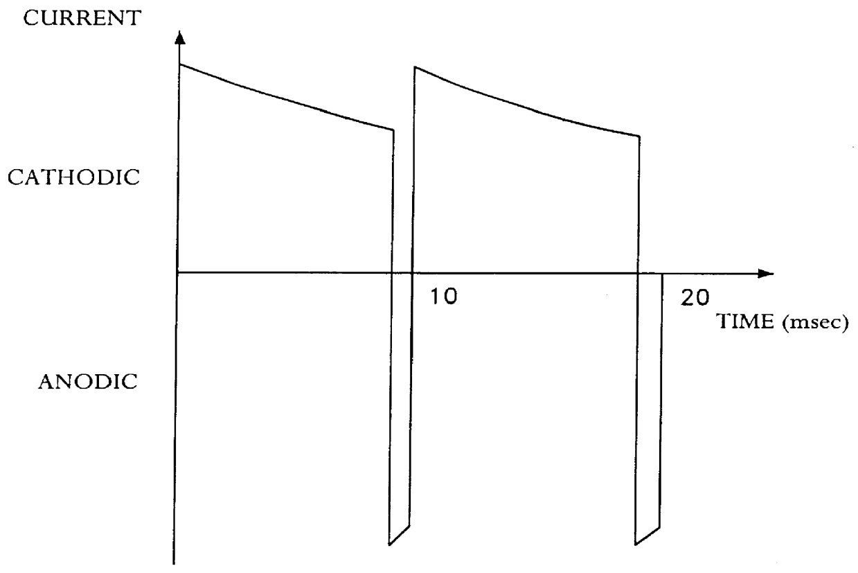
With the electrolytic solution used in Example 1, a copper coating was deposited by means of a pulse current procedure. The pulse current cycle according to FIG. 1 contained the following current pulses:

Current, cathodic: current density 4 A / dm.sup.2, duration 10 msec

Current, anodic: current density 8 A / dm.sup.2 ; duration 0.5 msec

Relative to the result from Example 1, the metal dispersion improved from 55% to 75%. However, no usable copper coatings could be obtained, since their appearance was unacceptable. The copper coating was simply matt. In addition the fracture elongation of the copper foil, which was deposited under these conditions, deteriorated from 21% to 14%.

example 3

COMPARATIVE EXAMPLE

example 1

with direct current. In the place of soluble copper anodes containing phosphorus, a titanium expanded metal, which was coated with mixed oxides, was used as a dimensionally stable, insoluble anode.

The deposited copper coatings were at first uniformly bright. The physical-mechanical properties were also satisfactory. However the metal dispersion values, which lay below the values given in Example 1, were measured. After a fairly long operation of the depositing bath, the appearance and the fracture elongation of the coatings deteriorated. At the same time, it was established that the mixed oxide coating of the titanium anode was eroded. This led to the over-voltage in the anode rising greatly.


PUM

PropertyMeasurementUnit
concentrationaaaaaaaaaa
current densitiesaaaaaaaaaa
temperatureaaaaaaaaaa

Abstract

PCT No. PCT/EP96/05140 Sec. 371 Date Apr. 23, 1998 Sec. 102(e) Date Apr. 23, 1998 PCT Filed Nov. 21, 1996 PCT Pub. No. WO97/19206 PCT Pub. Date May 29, 1997The invention relates to a method for the electrolytic deposition of metal coatings, in particular of copper coatings with certain physical-mechanical and optical properties and uniform coating thickness. According to known methods using soluble anodes and applying direct current, only uneven metal distribution can be attained on complex shaped workpieces. By using a pulse current or pulse voltage method, the problem of the coatings being of varying thickness at various places on the workpiece surfaces can indeed be reduced. However, the further problem of the geometric ratios being changed continuously during the depositing process by dissolving of the anodes is not resolved thus. This can be avoided by using insoluble anodes. In order to guarantee sufficient stability of the anodes and a bright coating even at those points on the workpiece surfaces, onto which the metal is deposited with high current density, it is essential to add compounds of an electrochemically reversible redox system to the depositing solution.

Description

The invention relates to a method for the electrolytic deposition of metal coatings with uniform coating thickness, particularly of copper coatings with certain physical-mechanical and optical characteristics.In order to achieve certain physical-mechanical properties in metal coatings, which can be deposited electrolytically, certain additive compounds must be added in small amounts to the deposition solution. Of main concern in this respect are organic materials, which have an effect on the bright finish, the levelling and the uniformity of the deposition on large surfaces, avoidance of so-called burnt-on particles, i.e. deposition of granular crystalline coatings and also the construction of metal coatings with high fracture elongation and tensile strength.The disadvantage in this respect is that these materials generally disintegrate during deposition, so that they have to be replenished during the operation. Admittedly, the observation of constant conditions in production is mos...

Claims


Application Information

Patent Timeline
Patent Type & Authority Patents(United States)
IPC IPC(8): C25D5/00C25D3/38C25D5/18H05K3/24
CPCC25D3/38C25D5/18H05K3/241Y10S205/92C25D5/627C25D5/623C25D5/617
Inventor DAHMS, WOLFGANGMEYER, HEINRICHKRETSCHMER, STEFAN
Owner ATOTECH DEUT GMBH
Why Eureka
Try Eureka