Fluid storage and dispensing system

a technology for gas dispensing systems and fluids, which is applied in the direction of pressure vessels, containers discharging from non-pressured vessels, chemical vapor deposition coatings, etc., can solve the problems of introducing a significant lag time to the dispensing operation, affecting the dispensing operation, and the provision of interiorly disposed heating coils or other heating elements in the zeolite bed itself, so as to minimize the possibility of impact and environmental exposure in use, prevent the e exit liquid liquid

Inactive Publication Date: 2000-08-15
ENTEGRIS INC
View PDF28 Cites 225 Cited by
  • Summary
  • Abstract
  • Description
  • Claims
  • Application Information

AI Technical Summary

Benefits of technology

A fluid pressure regulator is associated with the outlet port and may constitute part of a pressure regulator / phase separator assembly associated with the outlet port, e.g., at the neck of the vessel, to retain fluid in the vessel and, when the fluid is in liquid form, to prevent liquid from leaking to the dispensing valve and outlet. The pressure regulator and the optionally included phase separator are arranged to lie in the flow path of fluid dispensed from the vessel through the outlet port. The pressure regulator and the optionally included phase separator may be disposed interiorly or exteriorly of the vessel. Preferably, such elements are interiorly disposed, to minimize the possibility of impact and environmental exposure in use, and to minimize the leak path of the contained fluid from the vessel. When the pressure regulator and optionally included phase separator are interiorly disposed, the vessel may utilize a single weld or seam at the outlet port, to seal the vessel.
The phase separator may suitably comprise a porous membrane which is permeable to vapor or gas deriving from the liquid, but is not permeable to the liquid, and the phase separator is preferably disposed in a protective mode upstream of the pressure regulator so that when the contained fluid in the vessel is a liquid, the liquid is prevented from entering and interfering with the function of the pressure regulator in maintaining the liquid in the vessel, and preventing egress of liquid from the vessel.
The storage and dispensing vessel may be readily filled by setting the fluid pressure regulator at a suitably low pressure level so that the gas or vapor is at a pressure below the pressure regulator set point, using a conventional pressure regulator including a poppet element which may be biased with a biasing element such as a spring biasing element to a closed position, and which responds to pressure above the set point pressure by remaining closed, but which responds to pressure below the set point pressure by opening and allowing fluid flow therethrough.

Problems solved by technology

The method disclosed in the Knollmueller patent is disadvantageous in that it requires the provision of heating means for the zeolite material, to heat the zeolite to sufficient temperature to desorb the previously sorbed arsine from the zeolite in the desired quantity.
The use of a heating jacket or other means exterior to the vessel holding the arsine-bearing zeolite is problematic in that the vessel typically has a significant heat capacity, and therefore introduces a significant lag time to the dispensing operation.
Further, heating of arsine causes it to decompose, resulting in the formation of hydrogen gas, which introduces an explosive hazard into the process system.
Additionally, such thermally-mediated decomposition of arsine effects substantial increase in gas pressure in the process system, which may be extremely disadvantageous from the standpoint of system life and operating efficiency, as well as safety concerns.
The provision of interiorly disposed heating coil or other heating elements in the zeolite bed itself is problematic since it is difficult with such means to uniformly heat the zeolite bed to achieve the desired uniformity of arsine gas release.
The use of heated carrier gas streams passed through the bed of zeolite in its containment vessel may overcome the foregoing deficiencies, but the temperatures necessary to achieve the heated carrier gas desorption of arsine may be undesirably high or otherwise unsuitable for the end use of the arsine gas, so that cooling or other treatment is subsequently required to condition the dispensed gas for ultimate use.
Conventional high pressure gas cylinders are susceptible to leakage from damaged or malfunctioning regulator assemblies, as well as to rupture or other unwanted bulk release of gas from the cylinder if internal decomposition of the gas leads to rapid increasing interior gas pressure in the cylinder.

Method used


Image

  • Fluid storage and dispensing system
  • Fluid storage and dispensing system

Examples


Embodiment Construction

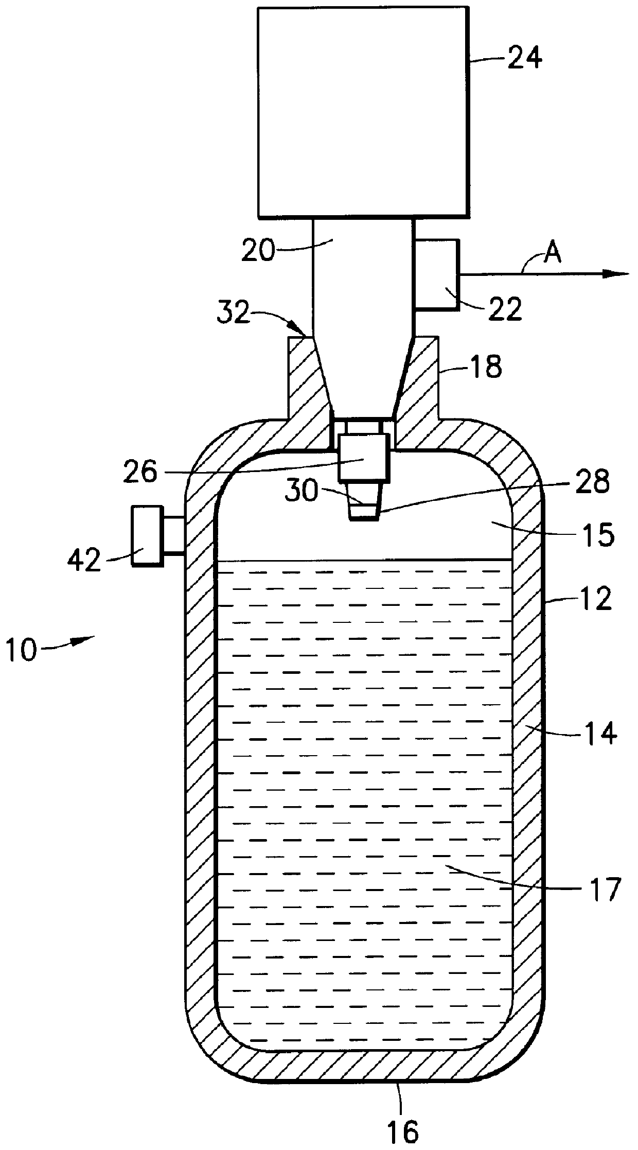
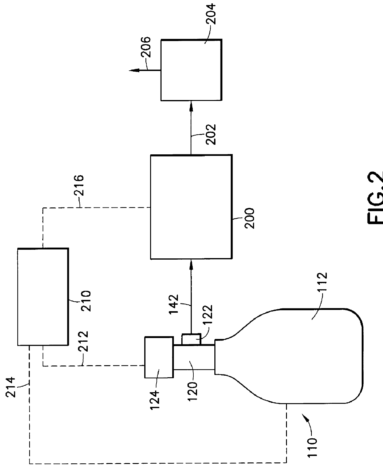
The present invention is based on the discovery that a fluid storage and dispensing system, of a type presenting an alternative to the fluid storage and dispensing system of Tom et al. U.S. Pat. No. 5,518,528, may be easily fabricated by disposing a fluid pressure regulator between a confined liquid volume and a gas dispensing assembly including a gas flow control element such as a gas flow shut off valve, mass flow controller, or the like.

Ancillary to this discovery is the finding that the fluid pressure regulator may be advantageously interiorly disposed in the fluid storage and dispensing vessel, so that it is protected by the vessel, e.g., cylinder casing or housing, from impact, environmental exposure and damage.

Although the fluid pressure regulator is preferably interiorly disposed in the fluid storage and dispensing vessel, it is possible to dispose such element exteriorly of the vessel in the broad practice of the invention. The invention therefore broadly contemplates the p...


PUM

PropertyMeasurementUnit
pressureaaaaaaaaaa
pore sizeaaaaaaaaaa
temperatureaaaaaaaaaa

Abstract

A fluid storage and dispensing system comprising a vessel for holding a fluid at a desired pressure. The vessel has a pressure regulator associated with a port of the vessel, and set at a predetermined pressure. A dispensing assembly, e.g, including a flow control means such as a valve, is arranged in gas / vapor flow communication with the regulator, whereby the opening of the valve effects dispensing of gas / vapor from the vessel. The fluid in the vessel may be constituted by a liquid which is confined in the vessel at a pressure in excess of its liquefaction pressure at prevailing temperature conditions, e.g., ambient (room) temperature. A phase separator such as a gas / vapor-permeable liquid-impermeable membrane, may be associated with the regulator, as a barrier to flow of liquid into the regulator, when the contained fluid in the vessel is in a liquid state.

Description

1. Field Of The InventionThis invention relates to a fluid storage and gas dispensing system which may be utilized to store high pressure liquid or other fluid, for dispensing of gas from the system for use in an application such as the manufacture of semiconductor products, such as semiconductor devices and materials.2. Description of the Related ArtIn a wide variety of industrial processes and applications, there is a need for a reliable source of process fluid(s).Such process and application areas include semiconductor manufacturing, ion implantation, manufacture of flat panel displays, medical intervention and therapy, water treatment, emergency breathing equipment, welding operations, space-based delivery of liquids and gases, etc.U.S. Pat. No. 4,744,221 issued May 17, 1988 to Karl O. Knollmueller discloses a method of storing and subsequently delivering arsine, by contacting arsine at a temperature of from about -30.degree. C. to about +30.degree. C. with a zeolite of pore siz...

Claims


Application Information

Patent Timeline
Patent Type & Authority Patents(United States)
IPC IPC(8): F17C13/00F17C11/00F17C13/04F17C1/00F17C13/02F17C7/00C23C14/24C23C16/448F17C7/02F17C7/04F17C9/02H01L21/205H01L21/265H01L21/306
CPCF17C1/00F17C7/00F17C7/02F17C11/00F17C11/005F17C13/02F17C13/025F17C13/04B01J20/20B01D53/0407B01D53/0415B01D53/053F17C13/045F17D1/04F17C2205/0338F17C2205/0391F17C2270/0518Y02E60/321B01D2253/10B01D2253/102B01D2253/104B01D2253/106B01D2253/1085B01D2253/202B01D2258/0216B01D2259/40003B01D2259/4009B01D2259/40094B01D2259/40098B01D2259/4525B01D2259/455F17C2201/0109F17C2201/0114F17C2201/058F17C2205/0329F17C2205/0341F17C2205/035F17C2205/0385F17C2223/0123F17C2223/033F17C2223/035F17C2250/043Y02E60/32F17C7/04
Inventor WANG, LUPINGTOM, GLENN M.
Owner ENTEGRIS INC
Why Eureka
Try Eureka