Multilayered coated cutting tool

Inactive Publication Date: 2000-08-15
SANDVIK INTELLECTUAL PROPERTY AB
View PDF10 Cites 166 Cited by
  • Summary
  • Abstract
  • Description
  • Claims
  • Application Information

AI Technical Summary

Benefits of technology

It is an object of this invention to avoid

Problems solved by technology

Furthermore, new developments of the existing PVD techniques by, for instance, intr

Method used


Image

  • Multilayered coated cutting tool

Examples


example

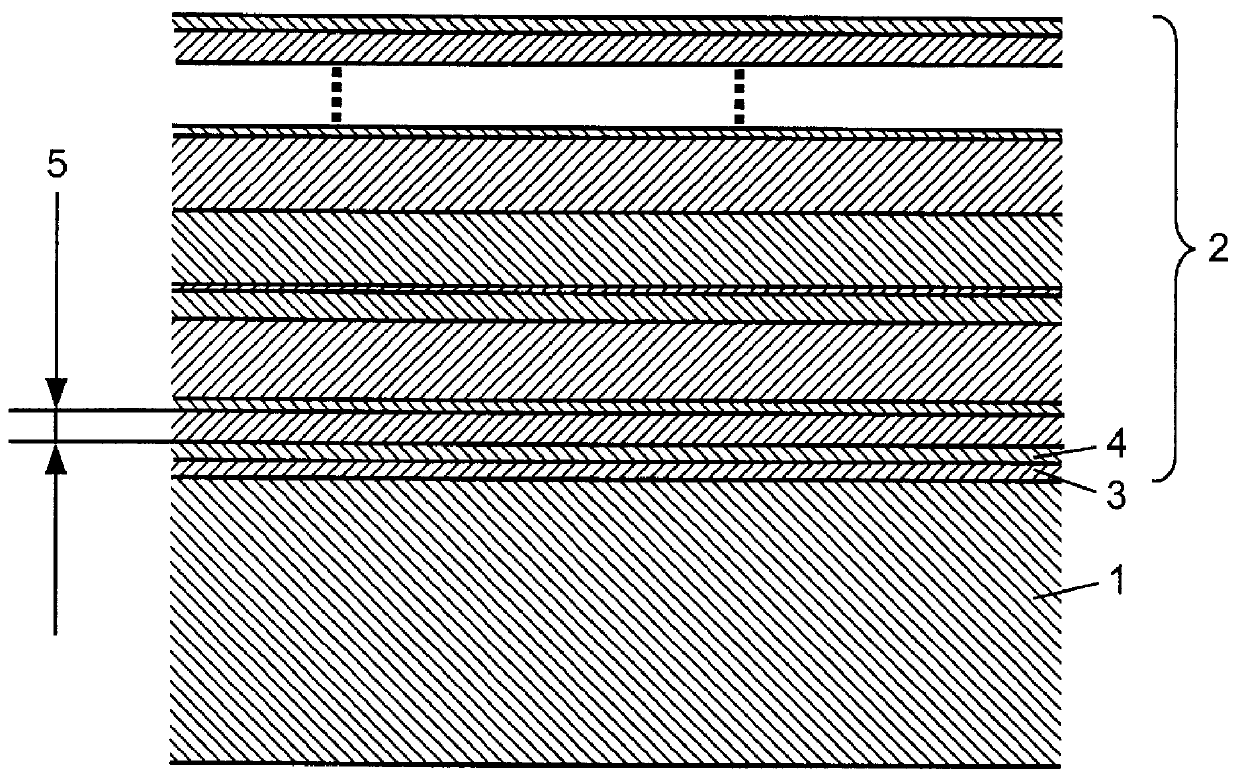
Aperiodic multilayers were deposited by reactive PVD-magnetron sputtering on thread-forming turning inserts made of cemented carbide (WC-10 w %Co). The two sputtering sources consisted of pure Ti and TiAl alloy, respectively, and sputtering was performed in an Ar / N.sub.2 gas mixture. The resulting total coating thickness was 3.0 .mu.m, and consisted of a TiN / Ti.sub.1-x Al.sub.x N, with x=0.50, multilayer having a sequence of individual lamellae layers with an aperiodic, i.e., nonrepetitive thickness. Cross-section transmission electron microscopy investigation revealed that the individual nitride layer thicknesses ranged from 2 to 15 nm, and the total number of layers exceeded 400.

In a thread turning operation, it was found that the flank wear resistance, effectively the tool service life, was improved markedly compared to both TiN and TiAlN single layer coatings having the same total thicknesses as the multilayer.


PUM

PropertyMeasurementUnit
Thicknessaaaaaaaaaa
Thicknessaaaaaaaaaa
Thicknessaaaaaaaaaa

Abstract

The present invention relates to a cutting tool comprising a body of sintered cemented carbide or cermet, ceramic or high speed steel on which at least one of the functioning parts of the surface of the body, a thin, adherent, hard and wear resistant coating is applied. The coating comprises a laminar, multilayered structure of refractory compounds in polycrystalline, non-repetitive form, MX/NX/MX/NX where the alternating layers MX and NX are metal nitrides or carbides with the metal elements M and N selected from the group consisting of Ti, Nb, Hf, V, Ta, Mo, Zr, Cr, Al and W. The sequence of individual layer thicknesses is essentially aperiodic throughout the entire multilayered structure, and layer thicknesses are larger than 0.1 nanometer but smaller than 30 nanometer, preferably smaller than 20 nanometer. The total thickness of said multilayered coating is larger than 0.5 mu m but smaller than 20 mu m.

Description

The present invention relates to a cutting tool for metal machining, having a substrate of cemented carbide, cermet, ceramics or high speed steel and, on the surface of said substrate, a hard and wear resistant refractory coating is deposited by Physical (PVD) or Chemical (CVD) Vapor Deposition. The coating is adherently bonded to the substrate and is composed of a laminar, multilayered structure of alternating metal nitrides or carbides with individual layers, or lamellae, having an aperiodic sequence of thicknesses. With this structure, it is understood that the multilayer has no superlattice repeat period. Individual metal nitride or carbide layers have thicknesses in the nanometer range (nm) and the metal elements of the nitride or carbide are selected from the group consisting of Ti, Nb, Hf, V, Ta, Mo, Zr, Cr Al, W and mixtures thereof.The present invention relates particularly to the art of PVD coated cemented carbides or similar hard materials such as cermets, ceramics and hi...

Claims


Application Information

Patent Timeline
IPC IPC(8): C23C14/06C23C30/00B23B27/14C23C28/04
CPCC23C14/0635C23C14/0641C23C28/044C23C30/005C23C28/42Y10T428/24942Y10T428/24975
Inventor SELINDER, TORBJORNSTRONDL, CHRISTIAN
Owner SANDVIK INTELLECTUAL PROPERTY AB
Why Eureka
Try Eureka