Method and apparatus for improved solar concentration arrays

a technology of solar energy and concentration array, which is applied in the direction of signal operation from vehicles, solid-state devices, railway components, etc., can solve the problems of high cost of solar cells, significant increase in the weight of cells, and extraordinarily high cost of placing a pound of weight, and achieve the effect of higher concentratio

Inactive Publication Date: 2000-09-12
NORTHROP GRUMMAN INNOVATION SYST INC
View PDF19 Cites 105 Cited by
  • Summary
  • Abstract
  • Description
  • Claims
  • Application Information

AI Technical Summary

Benefits of technology

One embodiment of the present invention is directed to photovoltaic concentrators comprising at least one photovoltaic cell for generating electrical power from incident solar radiation. The concentrator has at least one curved reflector. The reflector is directed to the radiation source and both concentrates and reflects the radiation to the photovoltaic cells located in the cell panel. The cell panel is angled toward the folding reflector. The use of a curved reflective concentrator results in a higher concentration ratio as compared to the use of flat reflective concentrators. Concentration ratios are in a range from about 6:1 to about 20:1.

Problems solved by technology

Designers of power systems for this application face numerous design constraints of which weight is one of the most critical.
The extraordinarily high cost of placing a pound of weight
This significantly increases the weight of the cells.
Still another constraint is the high cost of the solar cells.
These cells often are as much as 60% or more of the cost of the entire solar array.
Yet another constraint is the volume required to pack a solar cell array into a launch vehicle for containment while being launched.
For a concentrator array, key issues are: choice of concentration ratio; reflective versus refractive optics; cell choice and degradation analysis; array pointing accuracy (error tolerance); thermal control and operating temperature; and stowage and deployment approach and sequence.
Power generation degradation, i.e., reduced cell efficiency, is yet another constraint.
Higher temperatures reduce the power conversion efficiency of the cells.

Method used


Image

  • Method and apparatus for improved solar concentration arrays
  • Method and apparatus for improved solar concentration arrays

Examples


Embodiment Construction

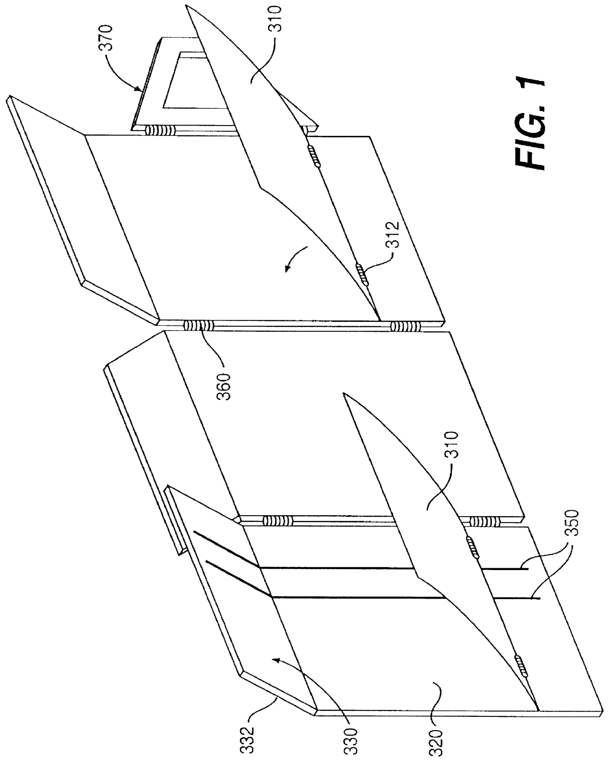
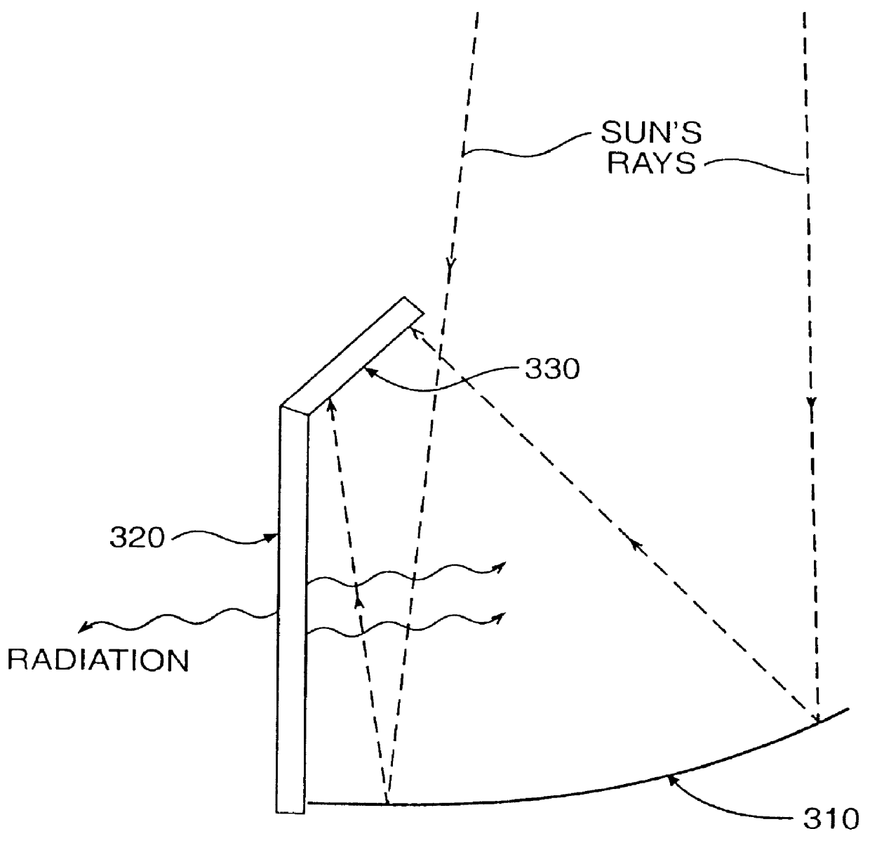
One embodiment of the present invention is directed to photovoltaic concentrator systems comprising at least two hinged sections with each section comprising a solar cell panel, a radiator panel, and a reflective concentrator panel. The solar cell panel comprises at least one photovoltaic cell for generating electrical power from radiation. These concentrator systems are applicable for the generation of power to a spacecraft. As such, stowage of the system becomes an issue. Usually, such a system employs two wings with each wing comprising at least two hinged sections. One wing systems are also utilized. Stowage volume and deployment weight are major considerations in the design parameters. Accordingly, the system is designed to be folded in a manner to reduce its stowage volume for transportation to space, thus adding limitations to the design parameters. The target is lighter, simpler and lower cost systems.

Each wing of the solar array comprises at least two sections, with three t...


PUM


Abstract

A lightweight photovoltaic concentrator is disclosed. The concentrator comprises at least two sections each comprising a cell panel, a radiator panel and a reflector panel. In one embodiment, the concentrator system of the present invention comprises at least two hinged sections each comprising a solar cell panel, a flat radiator panel, and a curved reflective concentrator panel. The solar cell panel comprises at least one photovoltaic cell for generating electrical power in response to radiation. The solar cell panel is aligned with the radiator panel at an angle less than 180 degrees but not less than 90 degrees facing the reflective concentrator panel. In another embodiment, the cell panels on adjoining sections are angled in opposite directions with respect to the radiator panels and wherein the reflective concentrator panels are located on opposite sides of the radiator panels. A heat pipe or loop heat pipe is located in the radiator panel to dissipate heat from the solar cells.

Description

FIELD OF THE INVENTIONThe present invention relates generally to an improved method and apparatus for employing photovoltaic concentrator arrays to generate electrical energy from concentrated solar energy.BACKGROUNDSolar cells which convert radiant energy from the sun into electrical energy are used to power spacecraft. Designers of power systems for this application face numerous design constraints of which weight is one of the most critical. The extraordinarily high cost of placing a pound of weightinto space is a serious constraint, and any improvement which can reduce the weight and still provide adequate performance is actively sought.Another constraint is the need for shielding the solar cells against radiation in regions of high fluence. This significantly increases the weight of the cells. Any arrangement which can reduce the area or volume that must be shielded is also actively sought.Still another constraint is the high cost of the solar cells. These cells often are as mu...

Claims


Application Information

Patent Timeline
Patent Type & Authority Patents(United States)
IPC IPC(8): B64G1/44B64G1/42F24J2/06F24J2/18H01L31/052H01L31/045B64G1/22B64G1/46B64G1/50F24S23/79H01L31/054H02S30/20
CPCB64G1/443F24J2/18H01L31/0547F24J2/4625H02S30/20H01L31/052B64G1/222B64G1/506F24J2002/5486Y02E10/40Y02E10/52F24S23/79F24S40/55F24S2030/16
Inventor LASHLEY, CHRISTOPHER M.KREIN, STEPHEN J.THORPE, ROSEMARY SCHMIDT
Owner NORTHROP GRUMMAN INNOVATION SYST INC
Why Eureka
Try Eureka