Disk drive rotary actuator system including synchronous counter torque generator

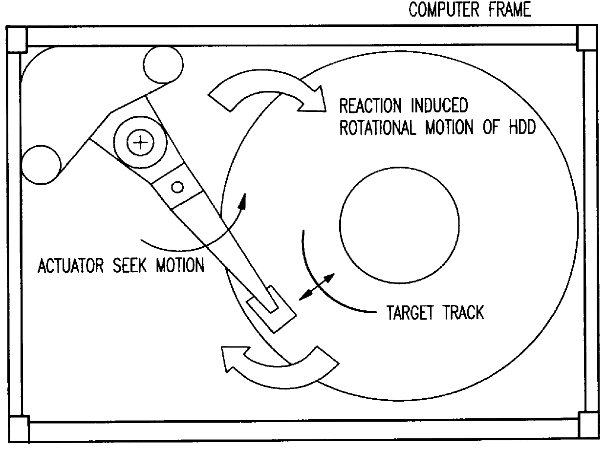
a rotary actuator and disk drive technology, applied in the direction of instruments, casings/cabinets/drawers, electrical equipment, etc., can solve the problems of disk drive being vulnerable to vibration excited by internal or external sources, prone to vibration of compliant objects, and prone to transient rotational vibration

Inactive Publication Date: 2000-09-19
HITACHI GLOBAL STORAGE TECH NETHERLANDS BV
View PDF7 Cites 47 Cited by
  • Summary
  • Abstract
  • Description
  • Claims
  • Application Information

AI Technical Summary

Benefits of technology

A second object of the present invention is to provide a disk drive system which is designed to be most robust against vibration.
Thus, with the invention, in the first case, an independent second actuator is electronically synchronized (or mechanically provided) to achieve zero net angular moment objective, whereas in the second aspect only a single torque generating seek actuator is used with novel modification. The second approach requires only one actuating device thereby contributing to lower component cost.
A third approach to the counter torque generation method is to keep the main voice coil motor (VCM) actuator as a single body pivoting about its pivot axis while allowing a rotating VCM magnet / yoke assembly to help reduce the reaction torque transmitted to the baseplate by a novel redesign. Thus, reaction torque is minimized by using the rotatable magnet / yoke assembly. Rotation is provided by mounting the magnet / yoke structure on a pivot system. The center of rotation of this pivot is made the same as that of the actuator with a ball bearing system being provided for the pivot.
Thus, the third approach not only cancels out the torque component but also reduces the net linear force acting on the baseplate at the pivot point. Since the mass and moment of inertia of the magnet / yolk structure is significantly greater than that of the actuator, the degree of motion allowed to the magnet / yoke structure can be much lower than the full motion the actuator will undergo.
A fourth approach exploits the HDD's spindle motor as the "dummy actuator" to generate the counter torque during the seek. This approach allows the existing spindle motor hardware to be exploited without additional cost. Provided that the track positioning information can be innovatively measured under varying motor speed, the actuator induced seek reaction torque is counter balanced by applying a counter torque to the spindle motor. Hence, the fourth approach involves a low cost solution employing the spindle motor itself as the "dummy" actuator.

Problems solved by technology

Therefore, the computer mounting frame is a compliant object prone to vibration.
Such a mounting configuration makes the disk drive vulnerable to vibration excited by internal or external sources.
The corresponding reaction torque on the baseplate causes transient rotational vibration that can be detrimental to the positioning accuracy of the read / write heads.
A major obstacle to raising the track density is inadequate head positioning accuracy in the presence of vibration disturbances.
Due to exponential growth in TPI, positioning the read / write elements over a track has become a major challenge.
Furthermore, the mechanical components such as spindle motor assemblies are not perfectly mass-balanced, and during operation they produce harmonic vibration.
When not compensated, a track following error of 15% of track pitch can be detrimental to a disk drive's "soft" and "hard" error rate performance.
However, the conventional mount design optimized to decouple internal spindle vibration remains susceptible to external input vibration.
While a unique isolation system could be developed in an attempt to solve vibration problems, it is difficult to commercialize an HDD if each computer manufacturer must achieve a design having low rotational vibrations.
Thus, as noted above, the seek reaction torque of an HDD acting on its baseplate that is mounted on a weak computer frame can cause a transient vibration.
The transient vibration problem arises from several mechanisms.
However, due to the high cost of a reliable and accurate sensor to detect fine motion, a sensor-based solution is considered to be less attractive in low cost HDDs.
Thus, the conventional hard disk drives suffer from serious problems which affect their performance in terms of seek time and the like in a disk drive.
The rotational vibration mode of the baseplate in a disk drive having a rotary actuator-based head positioning system causes a transient position error component.
With an ever increasing track density in magnetic disk drives, the reaction-induced vibratory component will degrade a disk drive's access time performance substantially.
The second approach requires only one actuating device thereby contributing to lower component cost.

Method used


Image

  • Disk drive rotary actuator system including synchronous counter torque generator
  • Disk drive rotary actuator system including synchronous counter torque generator
  • Disk drive rotary actuator system including synchronous counter torque generator

Examples


first embodiment

FIGS. 3A and 3B illustrate the concept of torque cancellation employing a dummy actuator according to a first embodiment of the present invention. The HDD includes a main actuator 1 having an inertia (I.sub.m) and driven by a current (i.sub.m). A torque constant of (k.sub.m) will produce an angular acceleration (i.sub.m *k.sub.m / I.sub.m)rad / s.sup.2. As shown, the main actuator has a voice coil motor (VCM) 2, a pivot 3, and read / write head 4.

A dummy actuator 5 has a similar arrangement including a VCM, pivot point, and a mass for balance, and has an inertia (I.sub.d) and is driven by a current (i.sub.d). A torque constant of (k.sub.d) will produce an angular acceleration (i.sub.d *k.sub.d / I.sub.d)rad / s.sup.2. Even though the main actuator 1 will be constrained to have minimum inertia and maximum angular stroke length required for a product, the dummy actuator 5 need not be limited to minimum inertia design. Based on space requirements, the dummy actuator 5 could be optimized to ach...

second embodiment

FIG. 8A shows another embodiment of the invention in which the counter torque generating element is external to the HDA assembly. This has the advantage that using a dummy actuator to increase settle out performance can be made optional to the end user. Thus, the dummy actuator can be easily retro-fitted to existing products or easily adapted to new products.

Further, this arrangement also precludes the need for two versions of the same structure (e.g., a high performance HDD with a dummy actuator and another with similar capacities but a slightly poorer settle-out time). A single HDD would suffice with the end user deciding if the extra cost of a dummy actuator was justifiable.

In FIG. 8A, the external dummy actuator is shown installed on the card side (e.g., the back side) of the HDD. This is because most 3.5" drives utilize a half-sized electronic card. The HDD real estate around the vicinity of the voice coil motor (VCM) is generally free. In the present invention, the dummy actua...

third embodiment

As shown in FIGS. 14-16, a third approach to generating counter torque is to form the main voice coil motor (VCM) actuator as a single body pivoting about its pivot axis, while allowing the VCM magnet / yoke assembly to help reduce the reaction torque transmitted to the baseplate by a novel redesign.

FIG. 14 shows an embodiment of the invention that provides reaction torque minimization using a rotatable magnet / yoke assembly 140. The torque, imparted to the actuator during a seek, results in a reaction torque on the baseplate of the HDD that is transmitted through the magnet / yoke structure 140 and the actuator pivot.

In the third embodiment, the reaction component is minimized by allowing the magnet / yoke structure 140 to rotate freely under this torque loading. Hence, the effective torque acting on the baseplate is minimized but not completely eliminated.

In FIG. 14, the rotation is provided by mounting the magnet / yoke structure 140 on a pivot system 141. The center of rotation of this p...


PUM

PropertyMeasurementUnit
frequencyaaaaaaaaaa
frequencyaaaaaaaaaa
timeaaaaaaaaaa

Abstract

A disk drive system, includes an arm for mounting a head, and at least one component, coupled to the arm, for being synchronized to maintain a zero net angular momentum of the arm and the at least one component. Another disk drive system including a read / write head, includes a torque counter-generating member for being synchronized to maintain a zero net angular momentum of the head.

Description

1. Field of the InventionThe present invention generally relates to a disk drive, and more particularly to a disk drive including a rotary actuator system for compensating for vibratory components during a seek time of a head of the disk drive.2. Description of the Related ArtPresent 2.5" and 3.5" disk drives (e.g., hard disk drives (HDDs)) are designed to operate in portable and desk-top / server environments, respectively. To reduce cost and weight of a computer system, manufacturers typically fabricate the HDD mounting frame utilizing thin structural members. Therefore, the computer mounting frame is a compliant object prone to vibration. Such a mounting configuration makes the disk drive vulnerable to vibration excited by internal or external sources. More specifically, a HDD with a rotary actuator system is highly sensitive to rotational vibration of its baseplate.Moreover, a head positioning servo system in an HDD performs several critical tasks.First, it moves the head to the v...

Claims


Application Information

Patent Timeline
Patent Type & Authority Patents(United States)
IPC IPC(8): G11B25/04G11B33/08G11B33/12
CPCG11B25/043G11B33/08G11B33/121
Inventor SRI-JAYANTHA, SRI MUTHUTHAMBYSHARMA, ARUNDANG, HIEN PHUKHANNA, VIJAYESHWARMCVICKER, GERARDSATOH, KIYOSHINAKAGAWA, YUZOKAGAMI, NAOYUKI
Owner HITACHI GLOBAL STORAGE TECH NETHERLANDS BV
Why Eureka
Try Eureka