Crown forming apparatus for forming crown floating type magnetic head

a technology of crown and magnetic head, which is applied in the direction of lapping machines, instruments, manufacturing tools, etc., can solve the problems of crown shape variation, and affecting the effect of forming

Inactive Publication Date: 2000-09-26
TDK CORPARATION
View PDF6 Cites 13 Cited by
  • Summary
  • Abstract
  • Description
  • Claims
  • Application Information

AI Technical Summary

Problems solved by technology

Since the surfaces of the floating type magnetic head and the magnetic recording medium, which confront each other, have high flatness, they are liable to be adsorbed by each other.
Thus, it is possible that a drawback is caused to the floating type magnetic head and the magnetic recording medium.
However, the first example of the conventional methods of forming a crown on a floating type magnetic head has a problem in that the shapes of crowns are liable to be varied because the formation of the crowns depends on the contraction of the wax 63 and the groove 62a of the groove jig 62.
The second example of the conventional methods of forming a crown on a floating type magnetic head has a problem in that a process is complicated and productivity is low because the cracks 73 must be formed by irradiating the laser beam 74 a plurality of times.
In addition to the above problem, the second example has a problem that the respective curvatures of the crown and the cross crown cannot be independently adjusted.
The third example of the conventional methods of forming a crown on a floating type magnetic head has a problem in that productively is low because the magnetic head sliders 81 are handled one by one.
In addition, the third example has another problem in that the shape of the crown is made to the convex surface which is convex in the longitudinal direction and the short direction of the magnetic head slider 81 and thus a crown which is convex only in the longitudinal direction of the magnetic head slider 81 cannot be formed.

Method used


Image

  • Crown forming apparatus for forming crown floating type magnetic head
  • Crown forming apparatus for forming crown floating type magnetic head
  • Crown forming apparatus for forming crown floating type magnetic head

Examples


Embodiment Construction

)

The effect of the crown heights of a bar on the relationship between the radius of curvature R.sub.2 of the processing surface of a lapping surface plate and the radius of curvature R.sub.1 of the convex surface of a jig was examined.

First, a wafer composed Al.sub.2 O.sub.3 --TiC ceramics was cut to approximately rectangular-prism-shaped bars.

Further, dummy bars having the same shape as the above bars and composed of Al.sub.2 O.sub.3 --TiC ceramics were prepared.

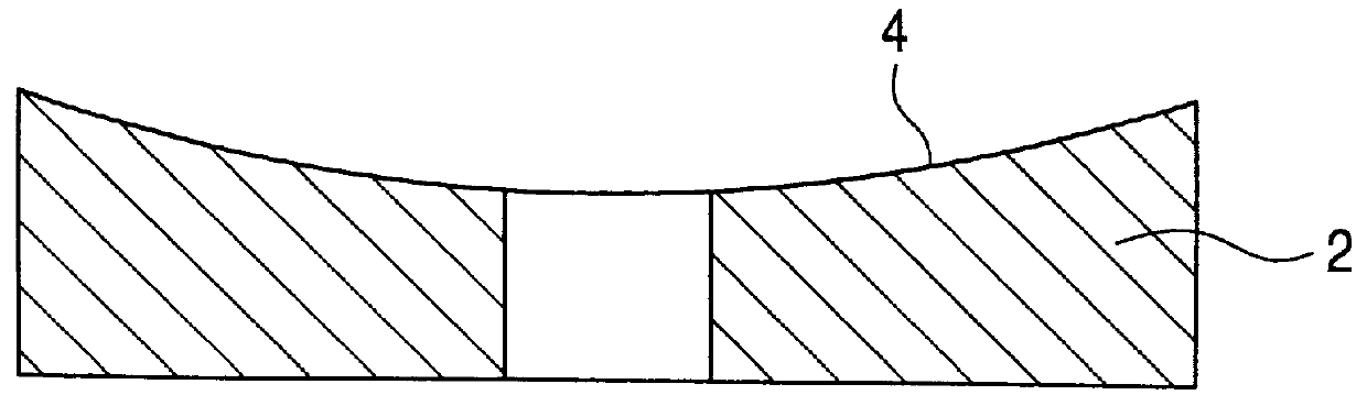
Next, a jig having a convex surface was prepared and elastic sheets composed of urethane having a width of 1 mm were bonded to the convex surface. Further, a bar and a dummy bar were deformed to an arc shape and bonded to the elastic sheets on the convex surface. The bar and the dummy bar were bonded to the jig in such a manner that they were spaced apart from each other in parallel with each other in the longitudinal directions thereof.

Jigs whose convex surfaces had radius of curvatures (R.sub.1) of 10.0 m and 12.0 m were ...


PUM

PropertyMeasurementUnit
thicknessaaaaaaaaaa
thicknessaaaaaaaaaa
thicknessaaaaaaaaaa

Abstract

Employed is a crown forming method of forming a crown on a floating type magnetic head which includes the steps of placing an approximately rectangular-prism-shaped bar, which has magnetic head elements of not less than 1 formed on a side wall thereof in a row, on the convex surface of a jig whose radius of curvature is R1 through an elastic sheet while facing the upper surface (surface to be processed) of the bar to a lapping surface plate having a concave processing surface whose radius of curvature is R2 with the relationship between the radius of curvatures set to R1>/=R2, deforming the bar to an arc shape along the longitudinal direction thereof and bonding it on the convex surface together with the elastic sheet, and lapping the upper surface (surface to be processed) by abutting it against the processing surface and moving the upper surface (surface to be processed) relative to a processing surface.

Description

1. Field of the InventionThe present invention relates to a crown forming apparatus for forming a crown on the floating surface of a floating type magnetic head.2. Description of the Related ArtFloating type magnetic heads record and reproduce information to and from magnetic recording mediums while floating therefrom.The floating type magnetic head is operated by a so-called CSS system in such a manner that it is floated from the magnetic recording medium by the movement thereof and placed on the magnetic recording medium again when it stops.Since the surfaces of the floating type magnetic head and the magnetic recording medium, which confront each other, have high flatness, they are liable to be adsorbed by each other. Thus, it is possible that a drawback is caused to the floating type magnetic head and the magnetic recording medium.To cope with this problem, the absorption between the floating type magnetic head and the magnetic recording medium is prevented by forming the floati...

Claims


Application Information

Patent Timeline
Patent Type & Authority Patents(United States)
IPC IPC(8): B24B41/06B24B37/04B24B37/30
CPCB24B37/30Y10T29/4905
Inventor NAKAGAWA, KOICHISUGAI, KATSUYAKOBAYASHI, HIDEAKINAKABAYASHI, ISAO
Owner TDK CORPARATION
Why Eureka
Try Eureka