3D imaging laser radar

Inactive Publication Date: 2000-10-17
CONTINENTAL AUTONOMOUS MOBILITY US LLC
View PDF3 Cites 168 Cited by
  • Summary
  • Abstract
  • Description
  • Claims
  • Application Information

AI Technical Summary

Benefits of technology

It is further the object of the present invention to provide sensors which detect and store target-reflected laser-light transit-time and pe

Problems solved by technology

Rastering is a slow process, particularly for large pixel-array sizes, and it requires cumbersome mechanical scanners and complex pixel-registration computer processing.
However, because of weight, cost and complexity problems, it is undesirable to obtain the entire image with independent, parallel, laser radar receivers, where each pixel uses a separate laser radar receiver system; multiplexing with one laser radar receiver should be used to make a large pixel-array imaging sy

Method used


Image

  • 3D imaging laser radar
  • 3D imaging laser radar
  • 3D imaging laser radar

Examples


Example

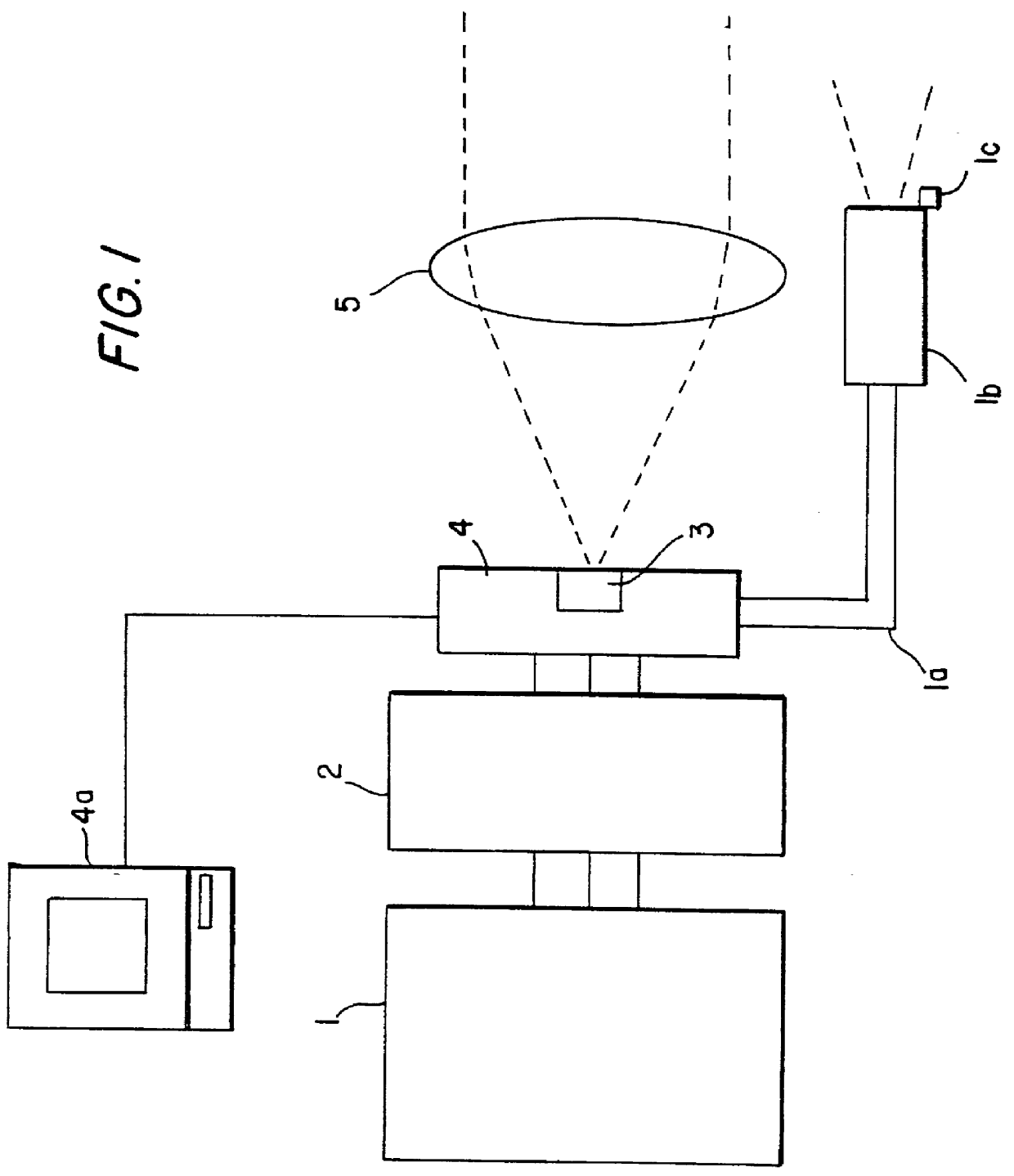
A preferred embodiment of the present invention, the Laser Radar Focal Plane Array (LR-FPA) imaging system depicted in FIG. 1, is designed to produce three-dimensional image data (area and range) from a single laser pulse reflected from objects in the atmosphere, using transit time information, and process the data to form a three dimensional image. Six parts make up the preferred embodiment of the invention; a pulsed laser 1, with delivery system 1a, collimator 1 and laser transmission detector 1c the data processing and laser control system 2; the sensor 3, and associated output and drive electronics 4, and the optics 5. The output and drive electronics 4 is electrically connected to an image processing computer 4a.

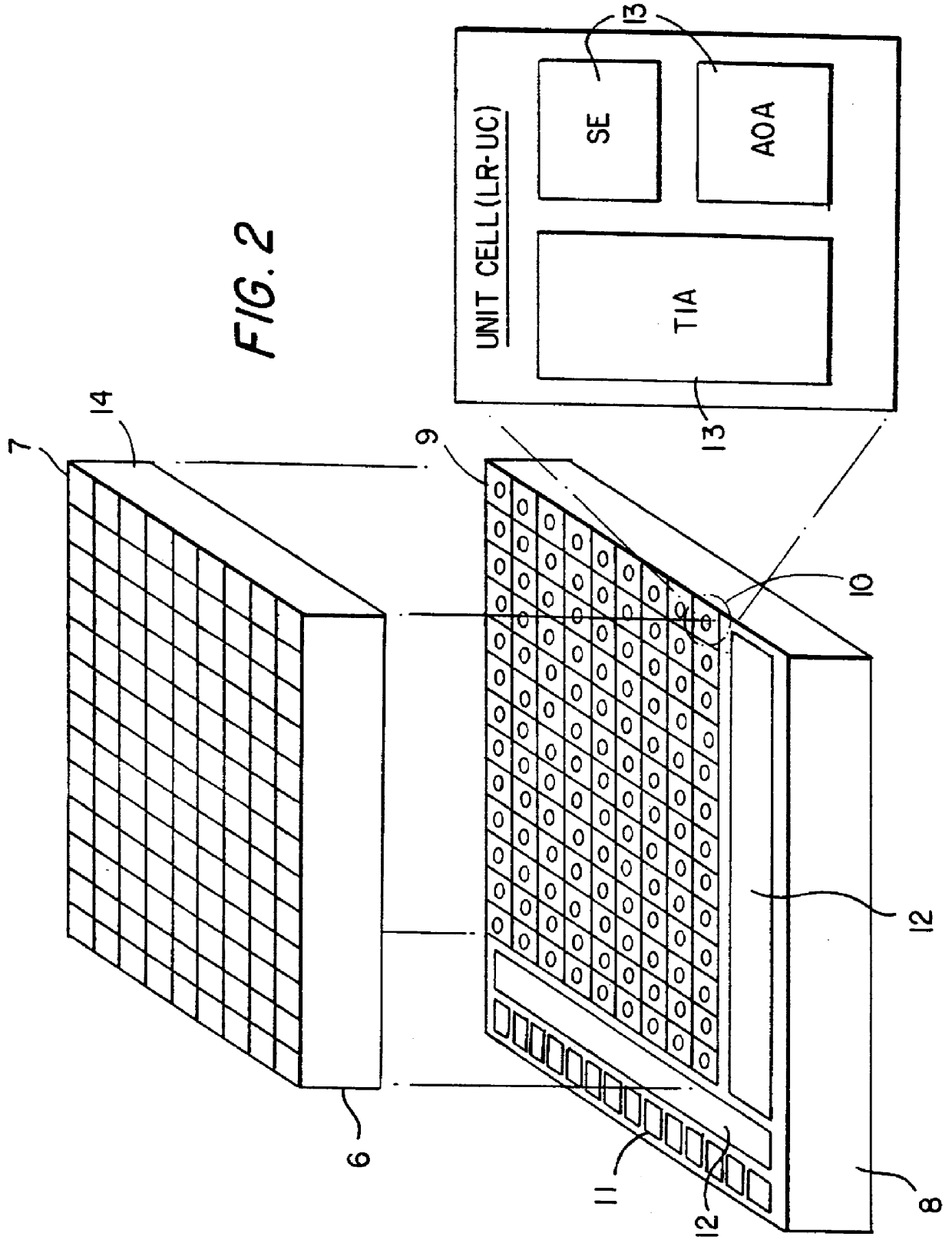
FIG. 2 shows one sensor design 3, a hybrid sensor, in greater detail. It consists of a detector array chip 6, composed of individual detectors 7, the laser radar processor chip 8, and indium bumps 9, which electrically connect each detector 7 to a single, corresponding,...


PUM


Abstract

A three dimensional imaging device is presented which uses single pulse from a pulsed light source for detecting objects enveloped by a light-transmitting medium such as the earth's atmosphere or free space. By means of switching off a ramping voltage, individually for each object pixel, the time of arrival of the reflected pulse is recorded. This time is related to the third object dimension. The device consists of the pulsed light source, optics for collecting the reflected light, a sensor for detecting the light, drive and output electronics for timing and signal conditioning of data generated by the sensors and a computer for processing the sensor data and converting it to a three dimensional image. The sensor collects and processes the light data in a unique manner, using a hybrid. The hybrid is actually a two dimensional array of collectors or detectors combined in very close proximity with their own processing electronics. In general, the hybrid is composed of two integrated circuit chips mated together. The two dimensional array defines two dimensions of the image. The processing electronics individually and independently switch off, at high-speed, a time varying voltage when the light pulse, reflected from the object, arrives at the sensor. The final voltages are stored and can be mathematically transformed to the third object dimension. The sensor also records peak light pulse information which can be used to obtain higher resolution in the third dimension.

Description

This invention relates to a laser radar vision apparatus capable of producing a three-dimensional image of a distant target.In particular, it relates to a lightweight, multiplexing, electronic apparatus for capturing a three-dimensional (3D) image of a distant target at high-spatial and high-range resolution in the atmosphere or in space with a single laser pulse.Laser radars (ladars) determine range in the atmosphere by measuring the transit time of a laser pulse from the transmitter / receiver to the target and dividing by twice the velocity of light in the atmospheric medium. Range resolution in such devices is related to the accuracy of this transit time measurement. In the atmosphere, ranges are typically measured in kilometers, where range resolution can be as small as 30 cm. A 3D target image can be obtained with a laser radar by rastering the laser beam across the target and measuring the transit time, pulse by pulse, where each pulse corresponds to a point on the target. The ...

Claims


Application Information

Patent Timeline
IPC IPC(8): G01S17/89G01S17/00G01S7/486G01S7/48G01S7/4863G01S17/894
CPCG01S7/4816G01S17/89G01S7/4863G01S17/894
Inventor STETTNER, ROGERBAILEY, HOWARD W.
Owner CONTINENTAL AUTONOMOUS MOBILITY US LLC
Why Eureka
Try Eureka