Structure and method for super FET mixer having logic-gate generated FET square-wave switching signal

a logic gate and super fet technology, applied in the direction of oscillation generators, modulation transference by distributed inductance and capacitance, electrical apparatus, etc., can solve the problems of inability to achieve high spur-free dynamic range (sfdr) and maintain low levels of distortion, system performance is limited to substantially lower levels, and the effect of reducing the number of transistors

Inactive Publication Date: 2000-11-07
DRS SIGNAL SOLUTIONS
View PDF26 Cites 127 Cited by
  • Summary
  • Abstract
  • Description
  • Claims
  • Application Information

AI Technical Summary

Problems solved by technology

Conventional frequency conversion or mixer stages in conventional RF systems have heretofore been unable to attain high levels of Spur-Free Dynamic Range (SFDR) and maintain low levels of distortion.
In fact such systems have been limited to substantially lower performance.
Another problem in conventional mixers used in tuners is that they typically perform the final stage mixing to baseband at a low Intermediate Frequency (IF) signal amplitude level, and then boost the amplitude of the final stage mixer output with a separate power amplifier to achieve the desired ADC signal level (typically in the range of from about 1 Volt to about 4 Volts peak-to-peak).
This baseband conversion approach only achieves approximately +43 dBm IP3 and +82 dBm IP2 into the ADC, may have unacceptable levels of distortion, and typically may not provide performance levels that keep with evolving state-of-the-art ADC dynamic range capability, or that meet the needs the end user.
In addition to the above described final mixer stage problems in conventional tuners, the first conversion stage of a tuner also significantly affects overall dynamic range, in fact so much so that degradation in the first stage may make it impossible to meet overall system performance requirements.
However, such a preamplifier gain stage in the signal path upstream from the mixer circuit undesirably increases the required IP3 and IP2 of the mixer by an amount equal to the added preamplifier gain.
Therefore, any system requirement for a preamplifier gain stage to increase sensitivity imposes even more severe constraints on other radio system components.
For example, such conventional mixers are relatively large (on the order of about 100 cubic inches), power inefficient (about 8 watts input power is needed to process 100 milliwatts--an efficiency of only about two percent (2%)), and expensive (for example, costing up to several hundred dollars per mixer).
Therefore, although some progress has been made in improving mixer performance to achieve high quality radio systems, such developments have not solved the need for compact, small form factor, light weight devices, having lower power consumption, long battery life in battery powered devices, at moderate to low cost.

Method used


Image

  • Structure and method for super FET mixer having logic-gate generated FET square-wave switching signal
  • Structure and method for super FET mixer having logic-gate generated FET square-wave switching signal
  • Structure and method for super FET mixer having logic-gate generated FET square-wave switching signal

Examples


Embodiment Construction

Reference will now be made in detail to the present embodiments of the invention, which are illustrated in the accompanying figures. We now turn to the drawings, wherein like components are designated by like reference numbers throughout the various figures.

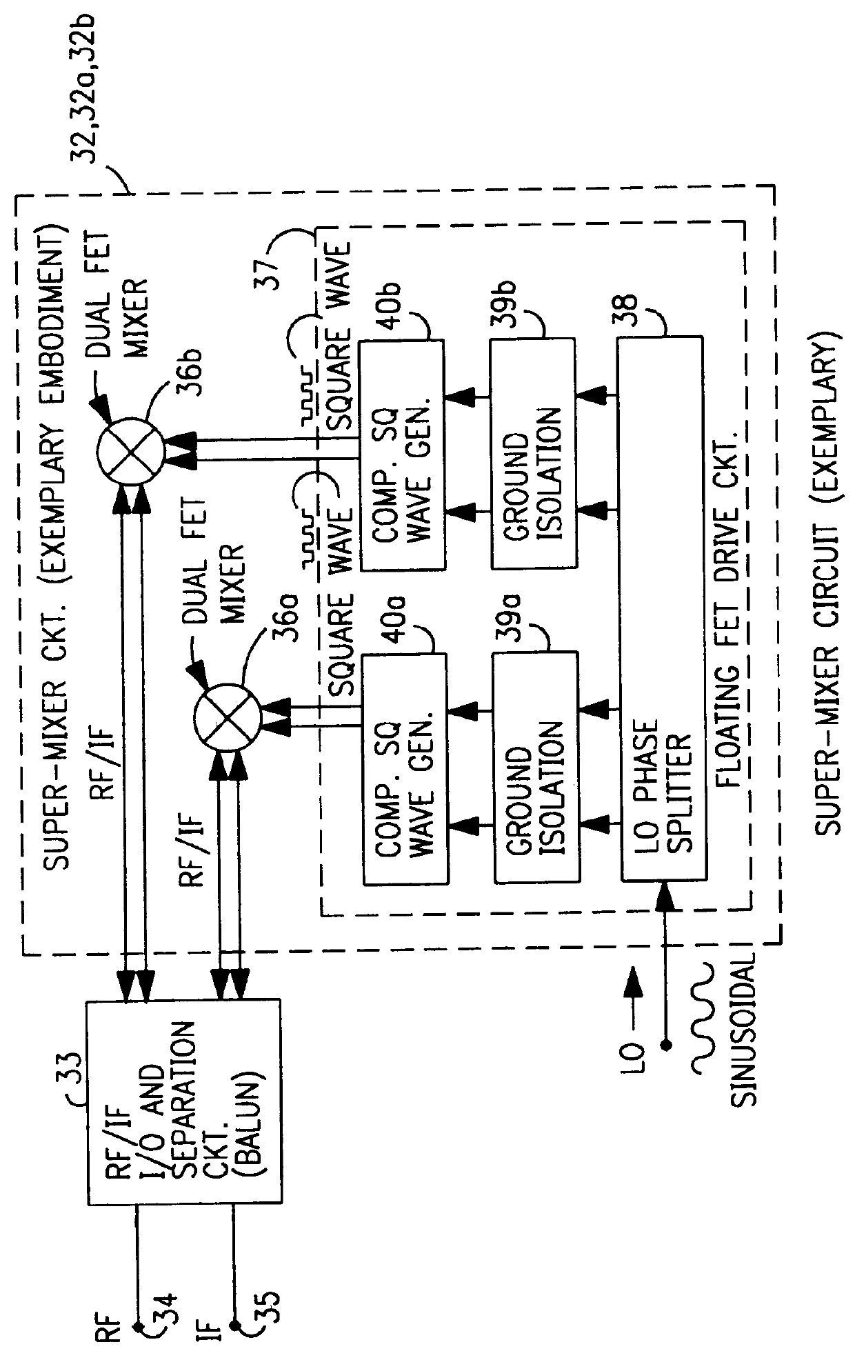
A simplified diagrammatic functional block diagram of an embodiment of a super-mixer 32 is now described relative to FIG. 1 which shows some of the significant features of the inventive super-mixer 32. In the embodiment shown, the super-mixer 32 is configured with and coupled to an RF / IF separation / filter circuit 33 (such as a balun) to operate as a passive reflection FET mixer wherein (when operating as a down-converter) RF energy is input to the RF / IF separation circuit at an RF port 34, and the IF output signal generated at the dual FET mixing devices 36a, 36b in a manner described hereinafter, is separated from the RF signal by the separation circuit at IF port 35. For an up-converter the roles of the RF and IF are reversed. ...


PUM


Abstract

A mixing method and mixer structure provide a circuit topology suitable for use in radio receivers, transmitters, tuners, instrumentation systems, telemetry systems, and other systems and devices performing frequency conversion in either homodyne or heterodyne implementations. The inventive mixer may be used for wireless communication devices including radios, cellular telephones, and telemetry systems whether land, sea, airborne, or space based, and whether fixed or mobile. The mixer provides superior intermodulation and harmonic distortion suppression and features excellent conversion loss, noise figure, port match, and port isolation as a result of its circuit topology. The mixer device circuit combines the advantages of series mixing FETs, a triple balanced design using a balanced passive reflection transformer, a precise local oscillator phase splitter, and square wave gate drive having high slew rate signal characteristics to achieve high levels of performance. It is power conservative and offers the advantage of long battery life in portable devices such as portable radios and cellular telephones as it requires only a modest amount of DC and local oscillator drive power, and is useful for operation over at least a multi-decade bandwidth.

Description

1. Field of the InventionThe invention relates generally to frequency conversion systems, devices, and methods, and more specifically to radio frequency communication devices and systems including, mixers, radio tuners, transmitters, and receivers incorporating FET mixer type frequency conversion devices for up- and down-frequency conversion.2. Background of the InventionConventional frequency conversion or mixer stages in conventional RF systems have heretofore been unable to attain high levels of Spur-Free Dynamic Range (SFDR) and maintain low levels of distortion. For example, the approximately 85-100 dB Spur-Free Dynamic Range required in certain tuner / receiver systems, particularly where the output of that mixer stage was intended as the input to high performance analog-to-digital converters (ADCs) where the 100 dB SPRD, is required at the input. In fact such systems have been limited to substantially lower performance. The last or final mixer stage just prior to output to the ...

Claims


Application Information

Patent Timeline
Patent Type & Authority Patents(United States)
IPC IPC(8): H03D7/14H03D9/06H03D9/00H03D7/12H03D7/00
CPCH03D7/1441H03D7/1408H03D7/1458H03D7/1466H03D7/1433H03D7/125H03D9/0658H03D2200/0088H03D2200/0023
Inventor VICE, MICHAEL WENDELLDEXTER, CHARLES EDWARD
Owner DRS SIGNAL SOLUTIONS
Why Eureka
Try Eureka