Engine-pressurized prestart oiler

a pre-start oiler and engine technology, applied in the direction of auxiliary lubrication, lubrication indication devices, lubrication elements, etc., can solve the problems of increasing the degree of drainage and the time required to reinstate proper lubrication, severe wear, and inability to maintain the engine, etc., to achieve the effect of simple, reliable, durable and minimal maintenan

Inactive Publication Date: 2000-11-21
JOHNS RALPH HOWARD
View PDF19 Cites 38 Cited by
  • Summary
  • Abstract
  • Description
  • Claims
  • Application Information

AI Technical Summary

Benefits of technology

It is an object of this invention that the means for performing the prestart lubrication require minimal modification to the engine, be adaptable as an easily retrofit assembly, and not materially alter normal engine operation.
It is an object of this invention that the means comprise an accumulator capable of storing oil and pressurized air for extended periods and in sufficient quantities to quickly and thoroughly perform the prestart lubrication.
It is an object of this invention that the means will perform the prestart lubrication, and prepare for subsequent use, with minimal inconvenience to the engine / vehicle operator.
It is an object of this invention that the means be simple, reliable, durable, and require minimal maintenance.

Problems solved by technology

Start-up of the engine inherently involves a period of inadequate lubrication.
Higher operating temperatures at shutdown and longer intervals of rest increase the degree of drainage and the time required to reinstate proper lubrication.
It is well recognized that severe wear can occur during the repeated cold starts to which internal combustion engines are typically subjected.
In addition to aggravated normal frictional wear as a result of inadequate lubrication, very harmful scoring of the bearing surfaces can occur.
It is generally acknowledged that well over half of all bearing wear may occur as a result of cold starts.
A problem with this type of accumulator is that the oil absorbs the pressurized air.
Thus, periodic maintenance to replenish the energy-storing air is a major disadvantage of this type of accumulator.
Although these designs may overcome the air absorption problem, other disadvantages are inherent.
Membranes, bladders, and diaphragms are subject to cracking and rupture.
Piston designs tend to be costly to manufacture, and wear and leakage may dictate periodic maintenance.
Other disadvantages of prior inventions involve the means of controlling oil flow between engine and accumulator.
As the operating pressure of a warm engine is much less than attained shortly after a cold start, much of the energy potentially available for prestart oiling is lost.
Among the disadvantages of this design is the increased potential for leaks due to additional connections in the conduit.

Method used


Image

  • Engine-pressurized prestart oiler
  • Engine-pressurized prestart oiler
  • Engine-pressurized prestart oiler

Examples


Embodiment Construction

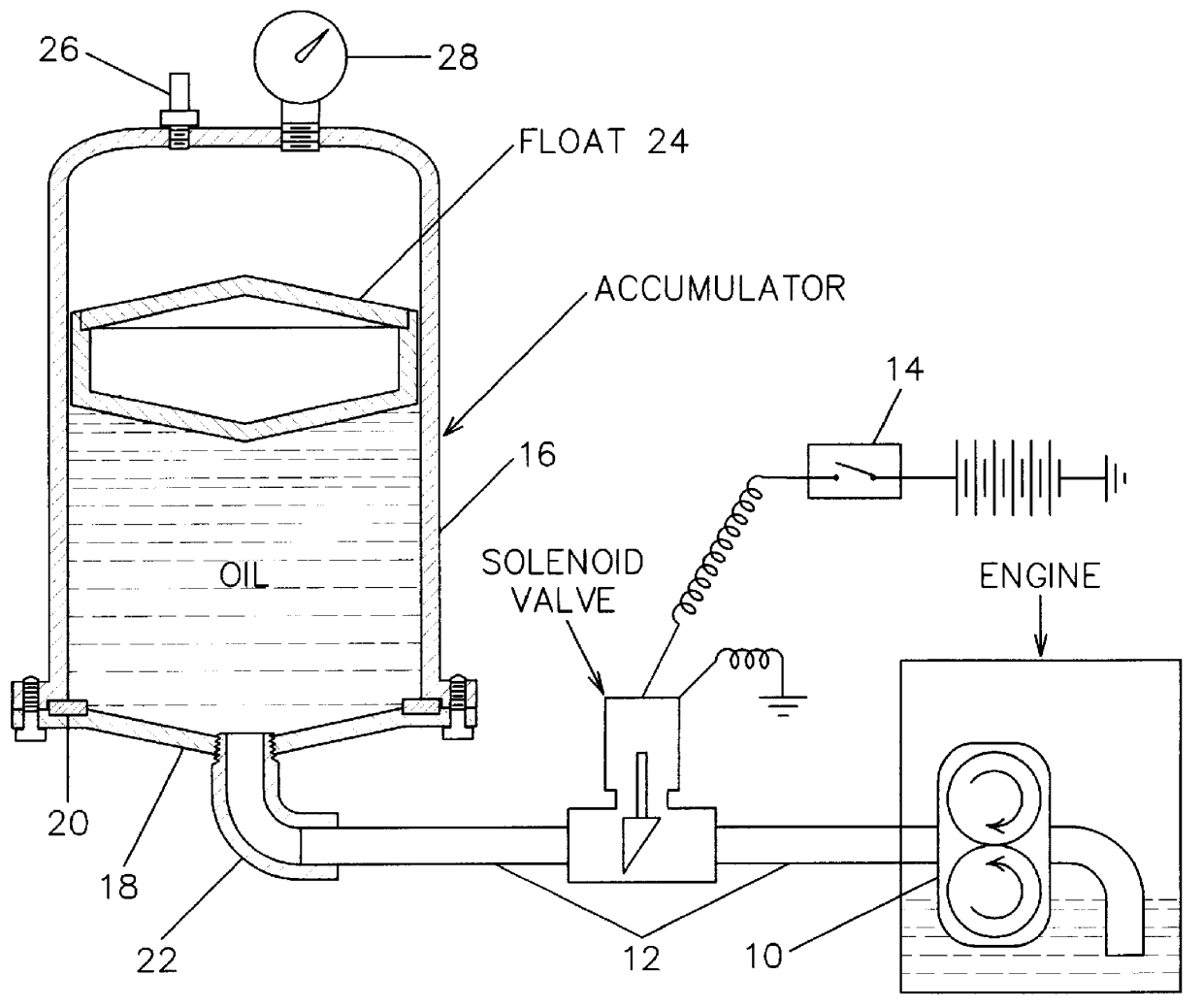
FIG. 1 provides an overview of the present invention, with the components drawn at various scales for clarity. In FIG. 1, an internal combustion engine or other machine having a pressure lubrication system is comprised of an oil pump 10 drawing oil from a sump. The oil pump delivers oil under pressure via galleries to various critical bearing surfaces. In the present invention, an oil conduit 12 connects the bottom of the accumulator to the engine pressure lubrication system. Means of attachment to the engine are detailed below in the discussion of FIGS. 5, 6 and 7. A solenoid valve, controlled by a normally open electrical switch 14, is interposed in the conduit and is detailed below in the discussion of FIG. 4.

FIG. 1, the accumulator for storing oil under pressure is comprised of a cylinder 16 with one formed, closed end. The other end is closed by an end cap 18 attached to the cylinder with a multiplicity of bolts. A seal 20 encircles the cylinder, end cap joint to prevent leakag...


PUM


Abstract

An engine-pressurized prestart oiler for an engine having pressure lubrication is provided, which rapidly lubricates critical engine bearing surfaces prior to the starting sequence. An accumulator for storing oil and pressurized air contains an air-oil separation float, which essentially fills the internal cross-sectional area and prevents absorption of the air. Discharge and recharge of the accumulator is preferably implemented by a normally closed solenoid valve. Discharge is controlled either manually by a switch or automatically by circuitry containing ignition-off time and accumulator pressure comparators, a starter interrupter, and a prestart oiling timer. Recharge is automatic, as the solenoid valve allows oil flow whenever the engine oil pressure sufficiently exceeds the accumulator pressure. A conduit connects the accumulator, solenoid valve, and engine, connecting to the engine either at the oil pressure sensor port or through an adaptor installed between the oil filter and the oil filter mount.

Description

1. Field of InventionThe instant invention relates to an apparatus for prestart oiling of any pressure-lubricated machine that experiences frequent periods of rest between intervals of operation.2. Description of Prior ArtDuring normal operation of an internal combustion engine, vital engine parts are supplied with oil by a pressure lubricating system. Oil is drawn from a sump by a pump driven by the running engine. The pump forces oil under pressure via galleries throughout the engine to vital bearing surfaces including the crankshaft, connecting rod, and cam bearings, and to the valve train.Start-up of the engine inherently involves a period of inadequate lubrication. When an engine is shutdown after an interval of operation, oil drains from the lubricating system including, to varying degrees, the bearing surfaces, oil galleries, pump, filter, and possibly an oil cooler. Upon restarting, the engine cranks and then may run for several seconds before the lubricating system refills ...

Claims


Application Information

Patent Timeline
Patent Type & Authority Patents(United States)
IPC IPC(8): F01M5/00F01M5/02
CPCF01M5/025F01M2005/028
Inventor JOHNS, RALPH HOWARD
Owner JOHNS RALPH HOWARD
Why Eureka
Try Eureka