Correction for parasitic voltages in resistance thermometry

a technology of resistance thermometry and parasitic voltage, applied in the direction of thermometers, instruments, electrical/magnetic means, etc., can solve the problems of dc voltage measurement subject to a number of errors, errors will swamp the very small signals that must be measured, and problems of its own natur

Inactive Publication Date: 2000-12-12
OXFORD INSTR NANOTECH TOOLS
View PDF10 Cites 20 Cited by
  • Summary
  • Abstract
  • Description
  • Claims
  • Application Information

AI Technical Summary

Problems solved by technology

However any DC voltage measurement is subject to a number of errors.
These may be caused by imperfections (offset voltage, offset current and bias current) in the electrical circuit used to measure the voltage and by thermocouple and other parasitic effects in the wiring used to connect to the sensor.
At the extremely low sensor excitation levels required to prevent sensor heating, these errors will swamp the very small signals that must be measured.
However high the quality of the amplifier used to detect the signals, the parasitic effects will cause problems.
However this introduces problems of its own.
At the relatively high resistance of the sensors being measured, stray capacitance on the wiring to the sensor and across the sensor itself introduces errors.
Moreover it is no longer possible to filter the sensor leads to prevent unwanted pick up from the environment, since such filtering would prevent the measuring signals reaching the sensor.

Method used


Image

  • Correction for parasitic voltages in resistance thermometry
  • Correction for parasitic voltages in resistance thermometry
  • Correction for parasitic voltages in resistance thermometry

Examples


Embodiment Construction

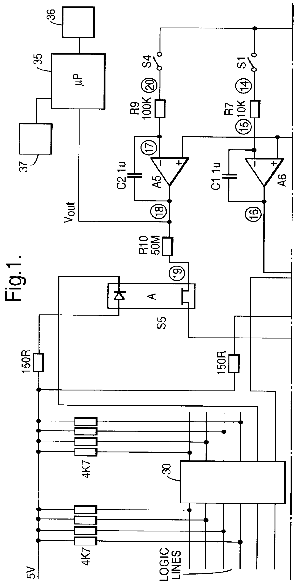
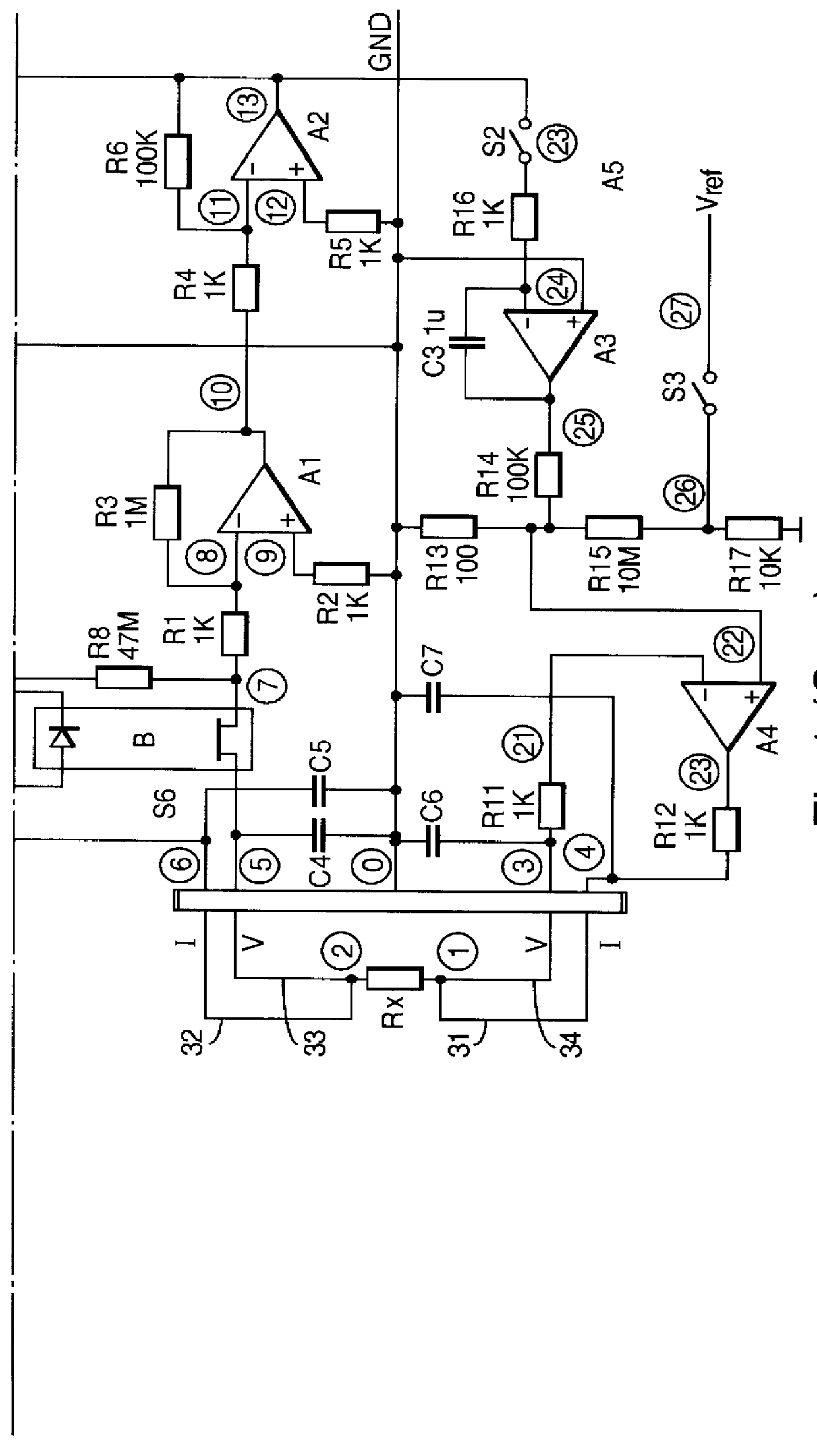
Referring to FIG. 1, the circuit nodes are given numbers in circles to allow easy identification. Node 0 is at "ground" potential with respect to this circuit.

Basics

Rx is the sensor resistor to be measured. It is located within a cryostat, remotely from the rest of the circuit at a temperature typically in the range of 5 mK to 10K. Four wires 31-34 are used to connect to this resistor and these run together within a single shielded cable. All these wires have 100 nF capacitors C4-C6 fitted, to prevent AC currents picked up on the leads passing through the sensor.

A1 and A2 together with resistors R1-R6 form a high gain, non-inverting, current-input amplifier with an overall conversion gain of 10.sup.8 volts per amp. (Thus a 10 nA change in the current flowing through R1, will result in a 1 volt change at its output, node 13). If this amplifier were "perfect", the presence of zero volts at node 13 would indicate that the input to the amplifier (i.e. node 7) is at exactly ground potent...


PUM

PropertyMeasurementUnit
temperatureaaaaaaaaaa
currentaaaaaaaaaa
voltageaaaaaaaaaa

Abstract

An apparatus employing a method for measuring the temperature of a sensor (Rx) having a resistance which varies in accordance with the temperature of the sensor, using a switching sequence to apply a parasitic voltage correction signal to the input of an amplifier in the measurement circuit whereby the sensor generates an offset response signal which is amplified and adjusted to substantially minimize the amplified offset response signal. The temperature of the sensor is calculated from the amplified response signal in accordance with a predetermined algorithm.

Description

The present invention relates to a method and apparatus for measuring the temperature of a sensor having a resistance which varies in accordance with the temperature of the sensor.DESCRIPTION OF THE PRIOR ARTIn order to measure the resistance of a sensor it is necessary to pass a current through the sensor and measure the voltage developed across the sensor by this voltage. Ohms Law then allows the resistance (or it's reciprocal, conductance) to be measured from the ratio of voltage to current. The current used may be either direct current (DC) or alternating current (AC).Direct current is easy to implement and has the advantage that the wires to the sensor may be heavily filtered to remove sensor heating due to AC current picked up from the environment. However any DC voltage measurement is subject to a number of errors. These may be caused by imperfections (offset voltage, offset current and bias current) in the electrical circuit used to measure the voltage and by thermocouple an...

Claims


Application Information

Patent Timeline
Patent Type & Authority Patents(United States)
IPC IPC(8): G01K7/24G01R27/14G01K7/16G01D3/028G01K7/01G01K7/00
CPCG01R27/14G01K7/24
Inventor SIMPSON, ALAN FERNLEY
Owner OXFORD INSTR NANOTECH TOOLS
Why Eureka
Try Eureka