
Ignition device for a discharge lamp and method for igniting a discharge lamp

a high-pressure discharge and discharge lamp technology, which is applied in the direction of lighting devices, light sources, electric lighting sources, etc., can solve the problems of not being able to accommodate the starting device of the lamp in the lamp cap, and the space requirement of known and commercially available starting devices is high

Inactive Publication Date: 2001-01-30
PATENT TREUHAND GESELLSCHAFT FUR ELECTRIC GLUEHLAMPEN MBH
View PDF7 Cites 18 Cited by
  • Summary
  • Abstract
  • Description
  • Claims
  • Application Information

AI Technical Summary

Benefits of technology

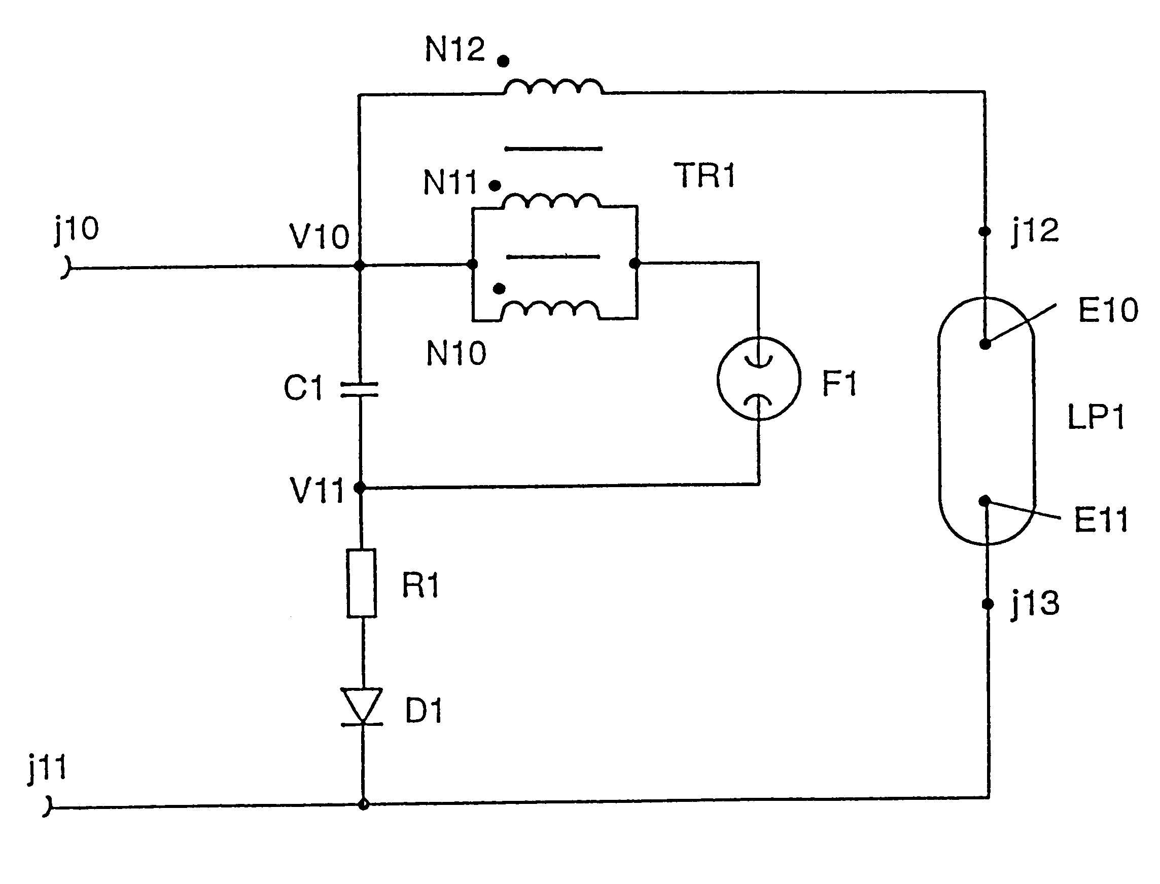
According to the invention, the starting device according to the invention has a transformer which has a parallel circuit, comprising at least two primary windings, and at least one secondary winding, the parallel circuit of the primary windings being inductively coupled to the at least one secondary winding. For a given transformation ratio of the transformer, this measure permits the number of turns per unit length on the secondary side of the transformer to be substantially reduced without the inductive coupling between the primary and secondary sides being impaired by the low number of turns per unit length of the primary windings. The induced voltage available on the secondary side does not change if the transmission ratio is preserved.
The reduction of the number of turns per unit length on the secondary side permits a compact design of the transformer and of the entire starting device, with the result that all the subassemblies of the starting device, including the transformer, can be accommodated in the lamp cap. The expensive electric connections, provided with insulation which is proof against high voltage, between the lamp holder and the starting unit are thereby eliminated. The high-voltage pulses for starting the gas discharge are then generated inside the lamp cap and are therefore no longer accessible from outside.
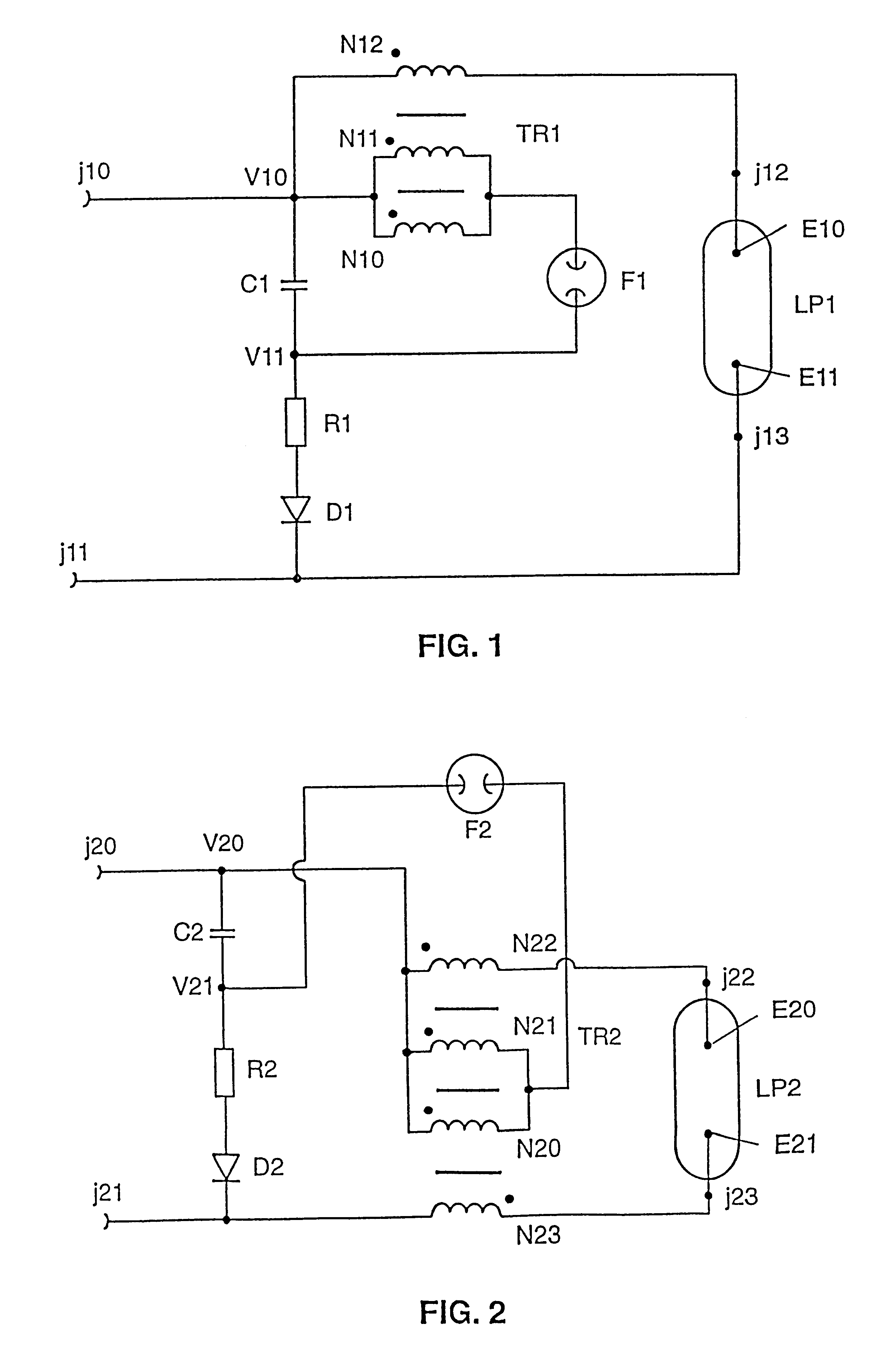
In the second, particularly preferred exemplary embodiment of the invention, the starting device is designed as a symmetrical pulse starting device which simultaneously applies unipolar starting voltage pulses of opposite polarity to the two gas discharge electrodes of the lamp. By contrast with the asymmetric pulse starting device, this mode of operation has the advantage of lower line losses and lesser demands on the electric insulation of the lamp parts conducting high voltage. The particularly preferred second exemplary embodiment of the pulse starting device has a transformer with two primary windings which are connected in parallel and through both of which, during the starting phase of the lamp, there flows the discharge current of the capacitor of the starting device, which capacitor discharges in surges via the switching path of the automatic switch, and two secondary windings, which are both inductively coupled to the parallel circuit of the primary windings. In each case, the two secondary windings are connected via a terminal of the starting voltage output to a gas discharge electrode of the lamp and are arranged in such a way that unipolar high-voltage pulses of opposite polarity are induced in the two secondary windings by the abovenamed discharging current.
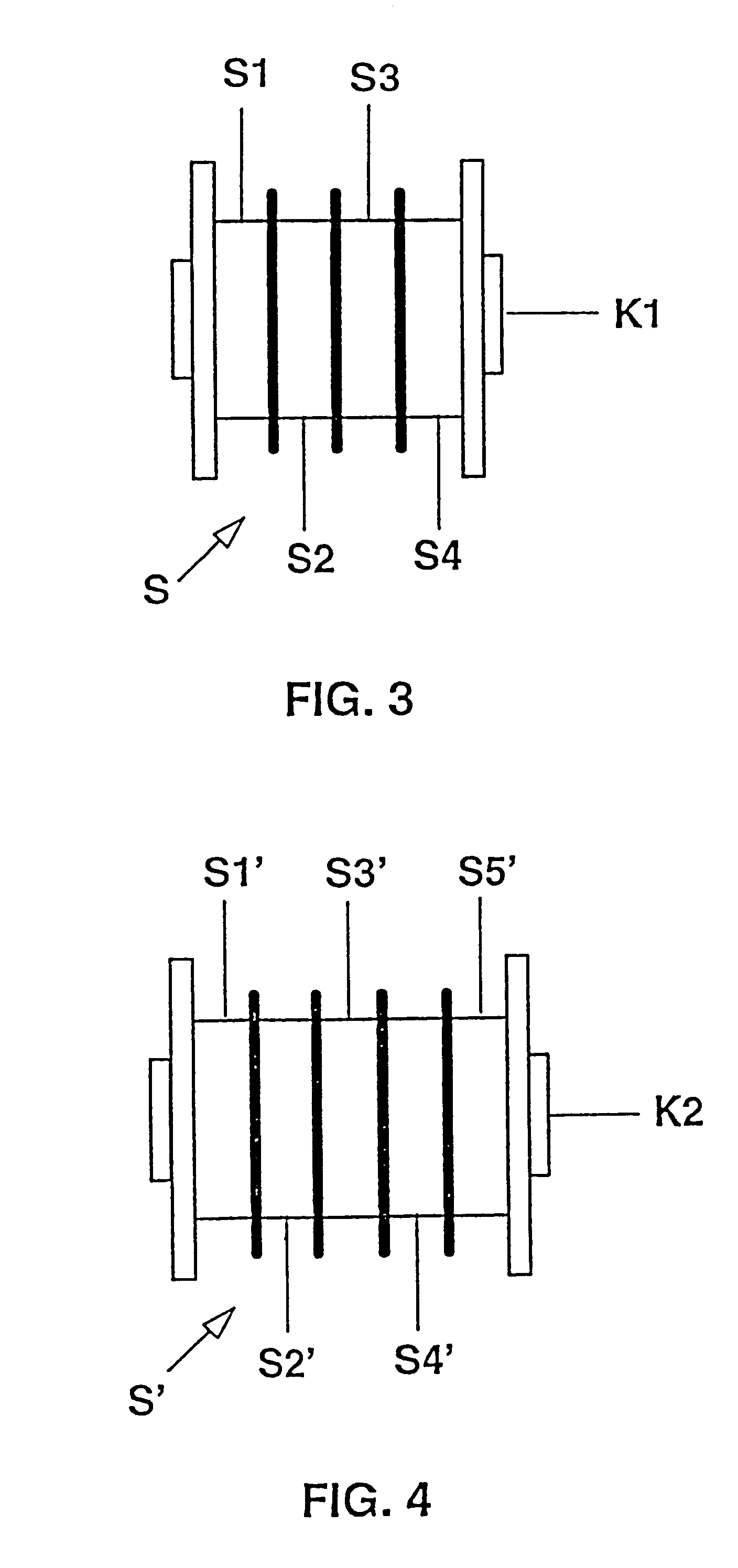
In the third exemplary embodiment of the pulse starting device, the transformer belonging to the starting device has a primary winding with at most two turns, which consists according to the invention of a wide metal strip which encloses the at least one secondary winding and advantageously also encloses the ferrite body of the transformer. For a given transformation ratio of the transformer, this measure permits the number of turns per unit length on the secondary side of the transformer to be reduced considerably without impairing the inductive coupling between the primary and secondary sides by the low number of turns per unit length of the primary winding. It has proved to be advantageous to use a transformer with a ferrite core and a coil former which has at least one chamber for the at least one secondary winding. To avoid electric breakdowns and to prevent eddy currents in the ferrite body, the ferrite core advantageously consists of a material which has an electric resistance of more than 1 M.OMEGA.. E cores or cylindrical cores, such as cylinder cores, tubular cores or threaded cores, for example, are advantageously used as ferrite body.

Problems solved by technology

As a consequence of the high transformation ratio of the starting transformer, the known and commercially available starting devices have a high space requirement because of the large volume of the starting transformer.
Consequently, in the case of low-wattage halogen metal vapour high-pressure discharge lamps which are provided for use in motor vehicle headlamps, it is not possible to accommodate the starting device for these lamps in the lamp cap.

Method used


Image

  • Ignition device for a discharge lamp and method for igniting a discharge lamp
  • Ignition device for a discharge lamp and method for igniting a discharge lamp
  • Ignition device for a discharge lamp and method for igniting a discharge lamp

Examples


Embodiment Construction

It is the object of the invention to provide an improved starting device for a discharge lamp, and an improved method for starting a discharge lamp. In particular, the starting device is intended to have as compact a design as possible, so that it can still be accommodated in the lamp cap even in the case of the low-wattage halogen metal vapour high-pressure discharge lamps which are used in motor vehicle headlamps and are of very small design.

This object is achieved according to the invention by means of the characterizing features of Patent Claim 1 or 13. Particularly advantageous embodiments of the invention are described in the subclaims.

According to the invention, the starting device according to the invention has a transformer which has a parallel circuit, comprising at least two primary windings, and at least one secondary winding, the parallel circuit of the primary windings being inductively coupled to the at least one secondary winding. For a given transformation ratio of ...


PUM


Abstract

The invention relates to a pulse starting device and a starting method for a discharge lamp, in particular a high-pressure discharge lamp for a motor vehicle headlamp. The starting device has a transformer which has either two primary windings which are connected in parallel and are both coupled inductively to the at least one secondary winding, or instead has a primary winding which consists of a wide metal strip and is wound, separated by an electric insulation, over the at least one secondary winding. The starting device according to the invention has a compact design which permits the complete starting device to be accommodated in the lamp cap.

Description

The invention relates to a starting device for a discharge lamp in accordance with the preamble of Patent Claim 1 or 12, and to a method for starting a discharge lamp.I. TECHNICAL FIELDThe invention relates in particular to a starting device for a high-pressure discharge lamp, for example a low-wattage halogen metal vapour high-pressure discharge lamp for a motor vehicle headlamp. The high-pressure discharge lamp has a discharge vessel which is sealed in a gastight fashion. Projecting into the discharge space are two gas discharge electrodes which are connected in an electrically conducting fashion to external supply leads. During operation of the discharge lamp, a light-emitting discharge arc is formed between its gas discharge electrodes. To operate the lamp, an operating unit is required which supplies the discharge lamp with electric power and limits the discharging current via the discharge arc. The operating unit also comprises a starting device for the discharge lamp which in...

Claims


Application Information

Patent Timeline
Patent Type & Authority Patents(United States)
IPC IPC(8): F21V19/00H05B41/04H05B41/00H05B41/18
CPCH05B41/042H05B41/04
Inventor HIRSCHMANN, GUENTHERBECKER, JUERGENBEHR, GERHARDWITTIG, CHRISTIANHELBIG, PETER
Owner PATENT TREUHAND GESELLSCHAFT FUR ELECTRIC GLUEHLAMPEN MBH
Learn More