Semiconductor integrated circuit capable of realizing logic functions

a technology of integrated circuits and semiconductors, applied in logic circuits, logic circuits, and logic circuits characterised by logic functions, etc., can solve problems such as large propagation delays along interconnections between basic cells (programmable logic blocks), and patents that do not disclose general techniques for realizing various logic circuits

Inactive Publication Date: 2001-02-27
KAWASAKI MICROELECTRONICS
View PDF25 Cites 22 Cited by
  • Summary
  • Abstract
  • Description
  • Claims
  • Application Information

AI Technical Summary

Problems solved by technology

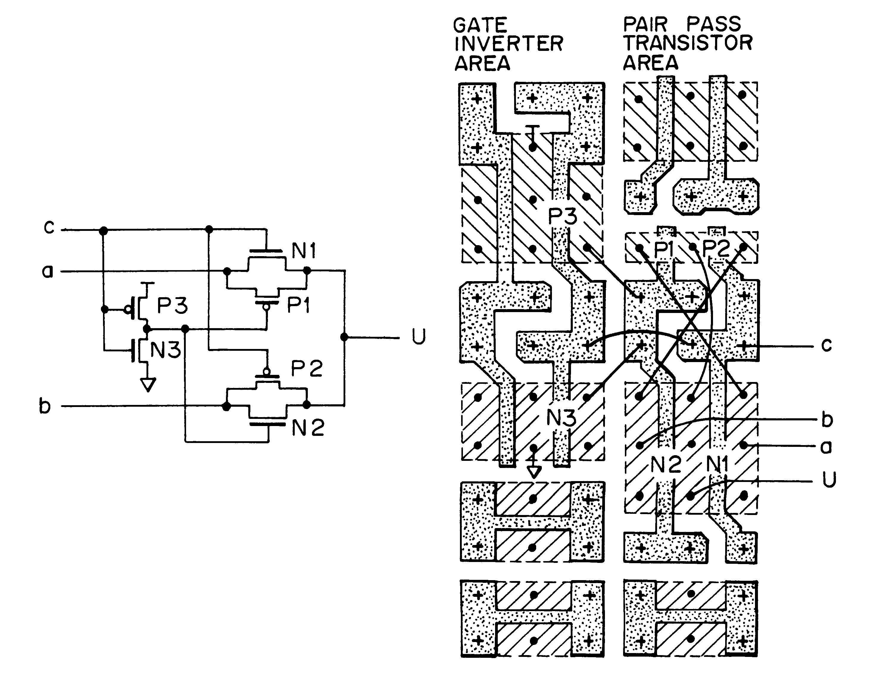
Although this patent discloses a technique of realizing a circuit for producing a C (carry) integral in the full adder, using six pass transistors and one triple-input NOR gate, the patent does not disclose a general technique to realize various logic circuits with a combination of pass transistors and a multiple-input logic gate, other than the circuit for producing a carry signal.
The inventors have recognized a problem that the number of required switching devices in conventional pass-transistor logic circuits can become larger than that of ordinary CMOS logic circuits, depending on the logical operation to be realized.
In the FPGA, large propagation delays occur along interconnections among basic cells (programmable logic blocks).
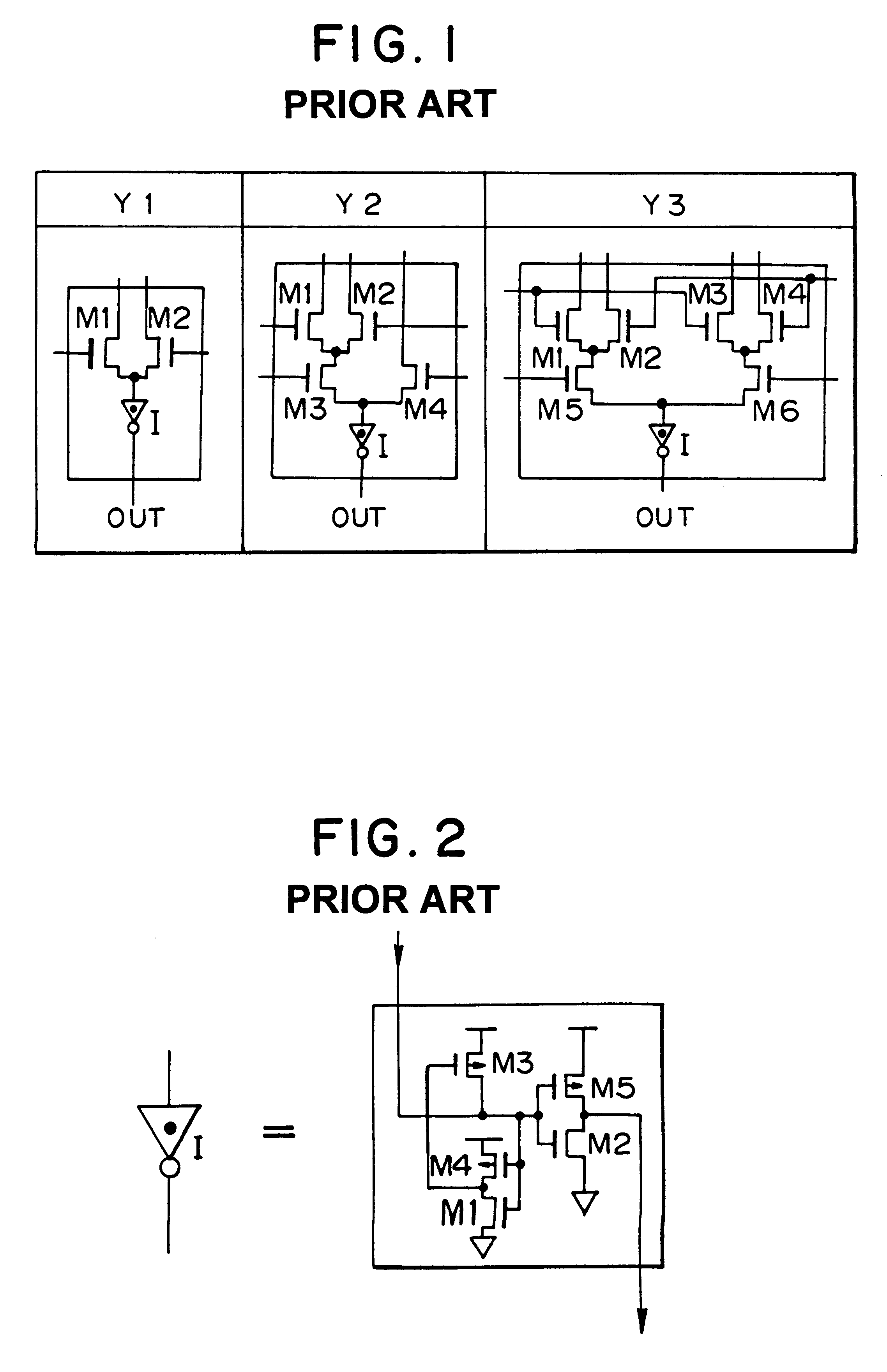
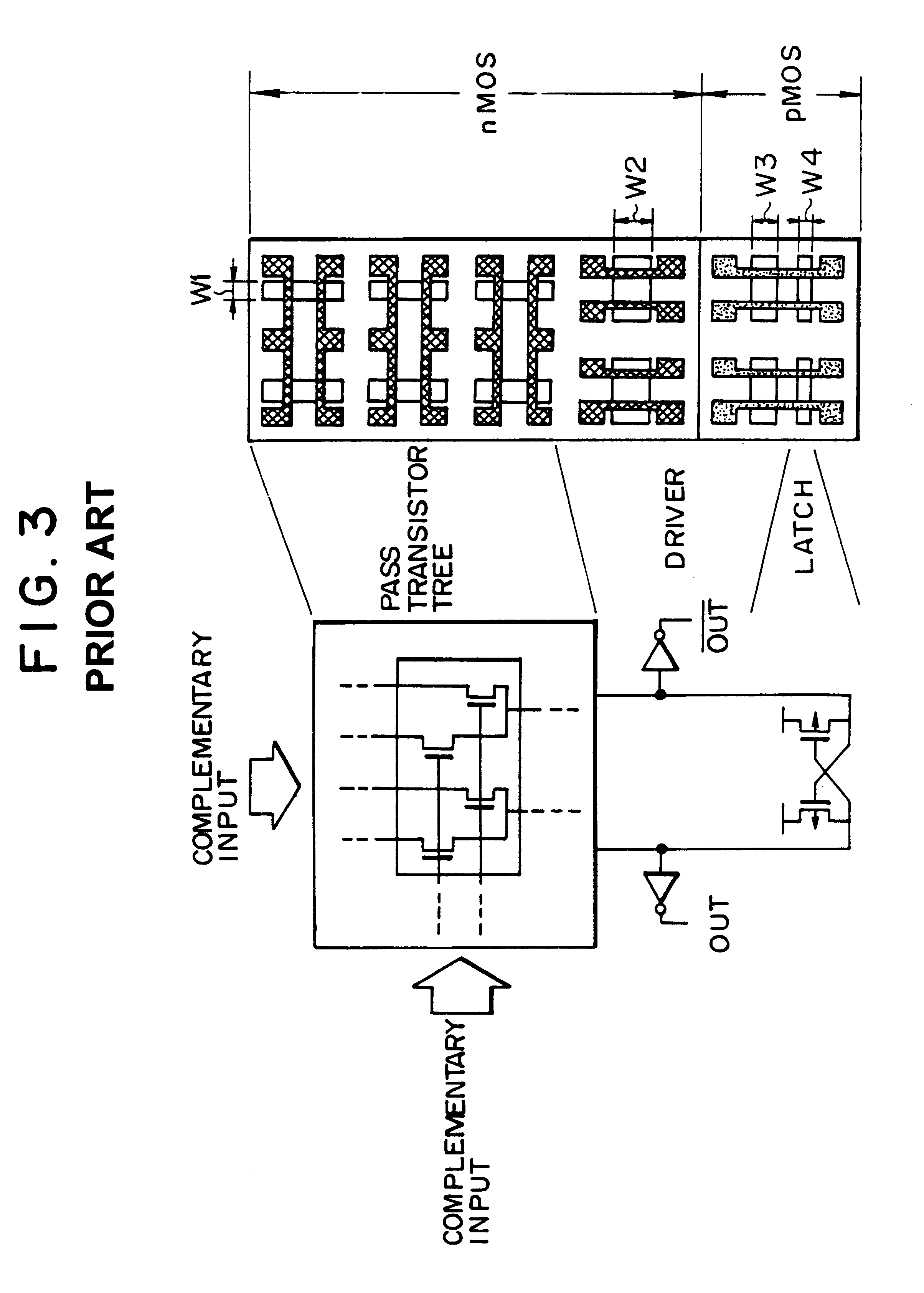
Therefore, there are some limitations in terms of the number of stages of the pass-transistor logic trees, the kinds of available multiple-input logic gate, and the number of intermediate input nodes thereof.
This imposes stricter limitations in terms of the selection or design of the logic circuit than the mask programmable gate array.
Since these programmable switches have a large series resistance and a large parallel capacitance, the interconnections among the blocks can cause great signal delays.

Method used


Image

  • Semiconductor integrated circuit capable of realizing logic functions
  • Semiconductor integrated circuit capable of realizing logic functions
  • Semiconductor integrated circuit capable of realizing logic functions

Examples


first embodiment

FIG. 7 is a block diagram illustrating the construction of a programmable logic block for use in a field programmable gate array according to the present invention.

As shown in FIG. 7, the programmable logic block of the present embodiment includes sub-logic blocks D1-D5. The interconnections among these sub-logic blocks in the programmable logic block are realized by interconnection elements N1-N10. The details of the sub-logic blocks D1-D5 are shown in FIGS. 8-12, respectively. The sub-logic block D1 is connected to the sub-logic block D3 via the interconnection elements N1 and N2. Similarly, the sub-logic block D2 is connected to the sub-logic block D3 via the interconnection elements N3 and N4. The sub-logic blocks D1, D2, and D3 are connected to the sub-logic block D4 via the interconnection elements N5, N6, and N7, respectively. The sub-logic block D3 is also connected to the sub-logic block D5 via the interconnection elements N8-N10.

The sub-logic blocks D1, D2, and D3 are also...


PUM


Abstract

A semiconductor integrated circuit is constructed with composite pass-transistor logic circuits serving as elementary circuit units each including a plurality of pass-transistor logic trees and a multiple-input logic gate. A wide variety of logical operations, even complex opearations, can be efficiently expressed using the composite pass-transistor logic circuit, and the resultant logic circuit can operate at a high speed. Thus, the semiconductor integrated circuit of the present invention can realize various logic functions required for various users in an efficient fashion. The present invention is particularly useful when applied to a field-programmable gate array integrated circuit, since complex logical operations can be expressed in a simple and efficient fashion by the composite pass-transistor logic circuits. The gate array integrated circuit obtained in accordance with the present invention can operate at a high speed with low power consumption. The present invention also discloses a basic cell suitable for use in an integrated circuit in the form of a gate array, and more particularly, a programmable logic block for use in a field programmable gate array integrated circuit.

Description

1. Field of the InventionThe present invention relates to a general-purpose semiconductor integrated circuit for realizing a variety of logic functions required in various applications by combining of a plurality of logic circuits expressing discrete logical operations. In the present invention, individual logic circuits are each constructed by combining pass-transistor logic circuits and a multiple-input logic gate. Complex logical operations can be efficiently expressed using the logic circuity disclosed herein, which can operate at a high speed. The present invention also relates to a method of forming the logic circuits used in such an integrated circuit, as well as a method of executing various logical operations.The present invention furthermore relates to a base cell used to construct a semiconductor integrated circuit in the form of a gate array, and more particularly, to a programmable logic block for use in a field programmable gate array integrated circuit. The present in...

Claims


Application Information

Patent Timeline
Patent Type & Authority Patents(United States)
IPC IPC(8): H03K19/094H03K19/01H03K19/20
CPCH03K19/1737
Inventor SAKO, NORIMITSU
Owner KAWASAKI MICROELECTRONICS
Why Eureka
Try Eureka