Electrostatic propulsion engine with neutralizing ion source

a technology of neutralizing ion source and electric propulsion engine, which is applied in the direction of reactive propulsion thrust device, plasma, electrical apparatus, etc., can solve the problems of accelerated and early material fatigue, high load and material demands, and large energy expenditur

Inactive Publication Date: 2001-03-06
DAMELERKLESLER AVIATION
View PDF8 Cites 27 Cited by
  • Summary
  • Abstract
  • Description
  • Claims
  • Application Information

AI Technical Summary

Problems solved by technology

Not only does this heating require a considerable expenditure of energy, but the required high cathode temperature leads to high loads and demands being placed on the material, which in turn leads to accelerated and early material fatigue.
Moreover, it is

Method used


Image

  • Electrostatic propulsion engine with neutralizing ion source
  • Electrostatic propulsion engine with neutralizing ion source
  • Electrostatic propulsion engine with neutralizing ion source

Examples


Embodiment Construction

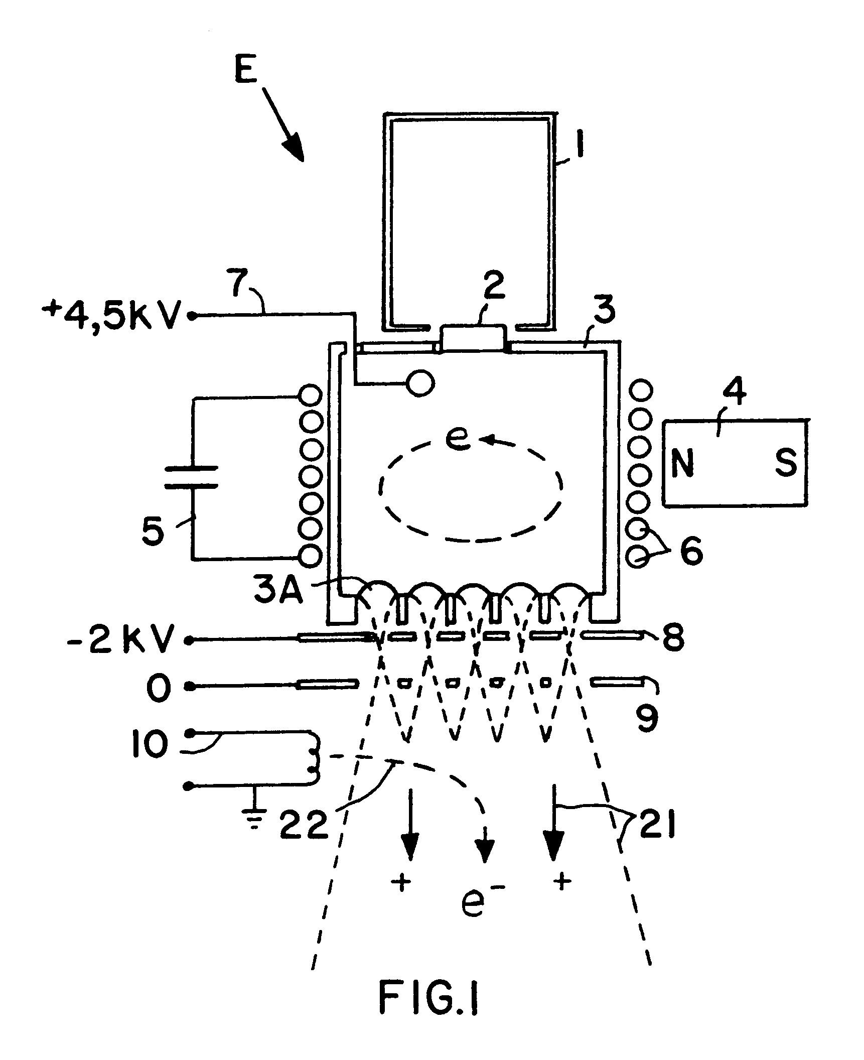
In the electrostatic propulsion engine or particularly the ion engine E shown in FIG. 1, a gas that is carried along in a supply container or tank 1, such as xenon gas in the present example embodiment, is emitted from the supply container 1 through a porous fritted member or frit 2 into a chamber 3 serving as an ionizing chamber 3. This chamber 3 is surrounded by a permanent magnet 4 and by a coil-shaped induction cathode 6 that is coupled to a resonant oscillating circuit 5. Moreover, an electron extraction anode 7 is arranged in the interior of the ionizing chamber 3.

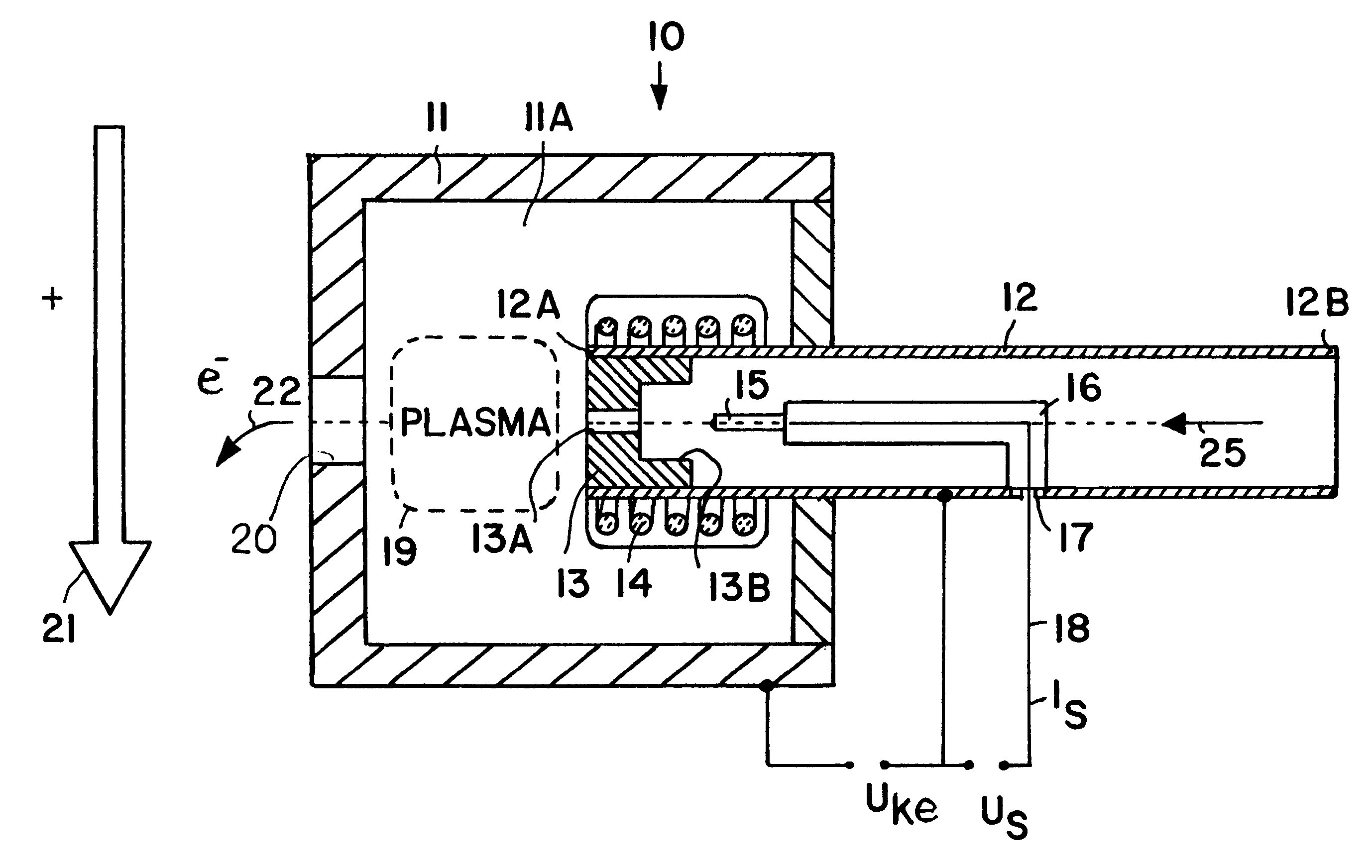
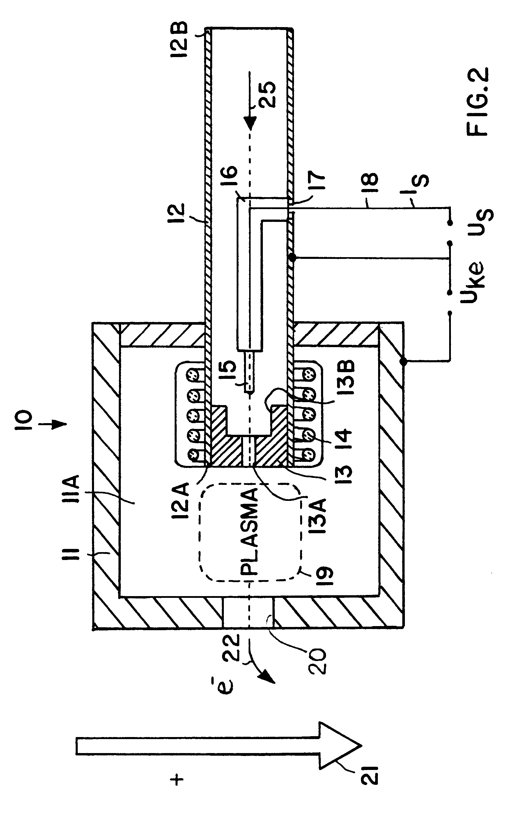
Ion outlet openings 3A are provided at the end of the ionizing chamber 3 opposite the gas inlet provided by the porous fritted member 2. An extraction or acceleration cathode 8 is arranged in front of the outlet openings 3A. A shielding electrode 9, also known as a retarding or decelerating electrode 9, is arranged spaced from the external extraction cathode 8. Moreover, a neutralizer 10 in the form of an electron so...


PUM


Abstract

An electrostatic ion propulsion engine for satellites and spacecraft is equipped with an electron source for neutralizing the propellant gas ion beam or jet emitted by the engine. The electron source includes an anode housing, a hollow cathode tube with gas flowing therethrough, a cathode element at the outlet end of the cathode tube within the interior space of the anode housing, and a pin- or rod-shaped auxiliary electrode arranged along the lengthwise axis in the hollow cathode tube. An ignition pulse is applied to the auxiliary electrode relative to the cathode tube, which causes a pulse discharge in the cathode tube, and in turn ignites the gas discharge between the anode and the cathode which generates the electron current.

Description

PRIORITY CLAIMThis application is based on and claims the priority under 35 U.S.C. .sctn.119 of German Patent Application 198 35 512.2, filed on Aug. 6, 1998, the entire disclosure of which is incorporated herein by reference.The invention relates to an electrostatic propulsion engine and particularly an ion engine for use in satellites and spacecraft, including an apparatus for ionizing a propellant gas, an apparatus for accelerating the propellant gas ions, and an electron source of which the output electrons are coupled or directed into the propellant ion jet for the purpose of neutralizing the same.BACKGROUND INFORMATIONIn conventional electrostatic propulsion engines of the above mentioned general type, atoms of a propellant gas expelled from a supply container or tank are first ionized to form positively charged propellant ions, and then these ions are accelerated in an electrostatic high voltage field to form a high-energy beam or jet of the ions which in turn provides a prop...

Claims


Application Information

Patent Timeline
IPC IPC(8): F03H1/00F03H99/00
CPCF03H1/0025
Inventor WALTHER, STEPHAN
Owner DAMELERKLESLER AVIATION
Why Eureka
Try Eureka