Fluid flow control valve

a flow control valve and flow control technology, applied in the field of flow control systems, can solve the problems of easy breakage of plastic or metal risers, inability to properly distribute water through sprinkler heads, and easy mechanical damage of risers, etc., to facilitate identification, facilitate sizing, and facilitate sizing.

Inactive Publication Date: 2001-03-13
WHETSTONE GRP INT
View PDF53 Cites 16 Cited by
  • Summary
  • Abstract
  • Description
  • Claims
  • Application Information

AI Technical Summary

Benefits of technology

In accordance with a further aspect of the present invention, a fluid flow control valve is disclosed for controlling flow through a fluid delivery section and a fluid delivery device of a fluid delivery system. The valve includes a housing connected to a first end of the fluid delivery section of the fluid delivery system. A valve seat is located within the housing between a first receptacle and a second receptacle. A keeper is positioned downstream from a stopper, which is movable between a first position located a distance away from the valve seat and a second position seated against the valve seat. The keeper, which can vary in length, has a first end positioned in close proximity to the stopper and a second end positioned in close proximity to the fluid delivery device. The keeper can comprise a plurality of rods stacked lengthwise within the fluid delivery system. Grooves spaced longitudinally along the rod can facilitate in sizing the rod to fit within a fluid delivery section having a length less than the length of the rod.
In accordance with yet another aspect of the present invention, a method for controlling fluid flow through a fluid delivery system involves providing a valve between a primary line and a secondary line of the fluid delivery system. The valve includes a movable stopper which selectively engages a valve seat to inhibit fluid flow through the secondary line. The stopper is positioned within the fluid flow through the primary line in a normal location under normal flow conditions. In this normal location, the stopper lies near the valve seat and in a position in which fluid flows on a side of the stopper opposite the secondary line. The stopper is maintained in the normal location under normal flow conditions. However, under abnormal flow conditions, the stopper is moved to a closed position. The stopper is seated against the valve seat when in a closed position to inhibit fluid flow through the secondary line under abnormal flow conditions. A fine stream of fluid can be projected from the valve to indicate that the valve is closed. This fine stream of fluid signals that a fault condition has occurred and facilitates in identifying the location of the closed valve.
In accordance with a further aspect of the invention, a method for controlling fluid flow through a delivery system involves providing a valve between a source of fluid and an effluent port of the fluid delivery system. The valve includes a movable stopper which selectively engages a valve seat to inhibit fluid flow through the effluent port. A stopper is positioned in an open position near the valve seat between the source of fluid and the valve seat in a position which allows fluid to flow through a passageway defined by the valve seat. A biasing device is positioned at least partially between the stopper and the valve seat and generally in contact with the stopper during normal flow conditions such that there is relative movement between the biasing device and the stopper. The stopper is maintained in the open position under normal flow conditions. The stopper is moved to a closed position under abnormal flow conditions such that the stopper seats against the valve seat when in the closed position to inhibit fluid flow through the effluent port under abnormal flow conditions. The biasing device can be sized to correspond with the effective length between a fluid delivery device of the fluid delivery system and the stopper, when the stopper is in the open position. The valve of this design can be used in a number of systems of various sizes because the biasing device can be easily sized to fit within the fluid delivery device and stopper.

Problems solved by technology

While the use of a riser-mounted sprinkler head enlarges the area irrigated by the sprinkler, the riser is susceptible to mechanical damage because it extends above ground in an exposed position.
Plastic or metal risers are thus easily broken (e.g., severed) or otherwise damaged (e.g., theft, vandalism, etc.), resulting most often in an open, free-flowing outlet.
When a riser is broken or the sprinkler is removed, water cannot be properly distributed through the sprinkler head.
Serious flooding and erosion consequently results in a small area, while the remainder of the area normally irrigated by the sprinkler goes unwatered.
A significant amount of water is wasted as the result of the unrestricted flow through the broken riser, and substantial soil erosion can occur.
In addition, the water fountain gushing from the broken riser also can pose a serious highway problem if the water sprays onto highway lanes, or if the resulting water and soil run-off flows onto the highway.
Numerous automobile accidents occur each year due to broken irrigation system risers.
While valves exist in the prior art for control of fluid flow in general, many such valves are inappropriate for restricting the flow of irrigation water through broken risers.
Prior valves are overly complicated and expensive for application to farm irrigation systems, which utilize hundreds of riser-mounted sprinklers.
Some devices which have been implemented for stanching the unrestricted flow of irrigation water have proven unreliable, often failing to stop or even slow the rate of water flow when a riser breaks or other failure occurs.
Other prior devices are too sensitive, shutting down water flow to undamaged risers.
In addition, when prior devices do function to stop the flow of water through a broken riser, the broken sprinkler often remains undetected for days, leaving the area surrounding the broken sprinkler unwatered.
This danger is especially true of farm irrigation, where a single broken riser in a large field with many sprinklers could easily escape notice for many days, damaging crops in the vicinity.
Further deficiencies in prior devices include an inability of these devices to cope with transient flow conditions.
For instance, the prior devices may prematurely shut off the valve in response to the combination of air and water in the system that often occurs when the system is first turned on.
In addition, prior devices often include improperly restrained components which vibrate and wear under normal flow conditions.
Prior devices also have close fitting parts which are subject to corrosion.
As a result, the small space between the parts cannot be maintained as corrosion, scale, debris, etc., often fill the space between the closely fit parts, and the device is likely to malfunction.
Upon corrosion, however, the disc or poppet will not properly seal the valve seat, thereby allowing fluid flow within the valve.

Method used


Image

  • Fluid flow control valve
  • Fluid flow control valve
  • Fluid flow control valve

Examples


Embodiment Construction

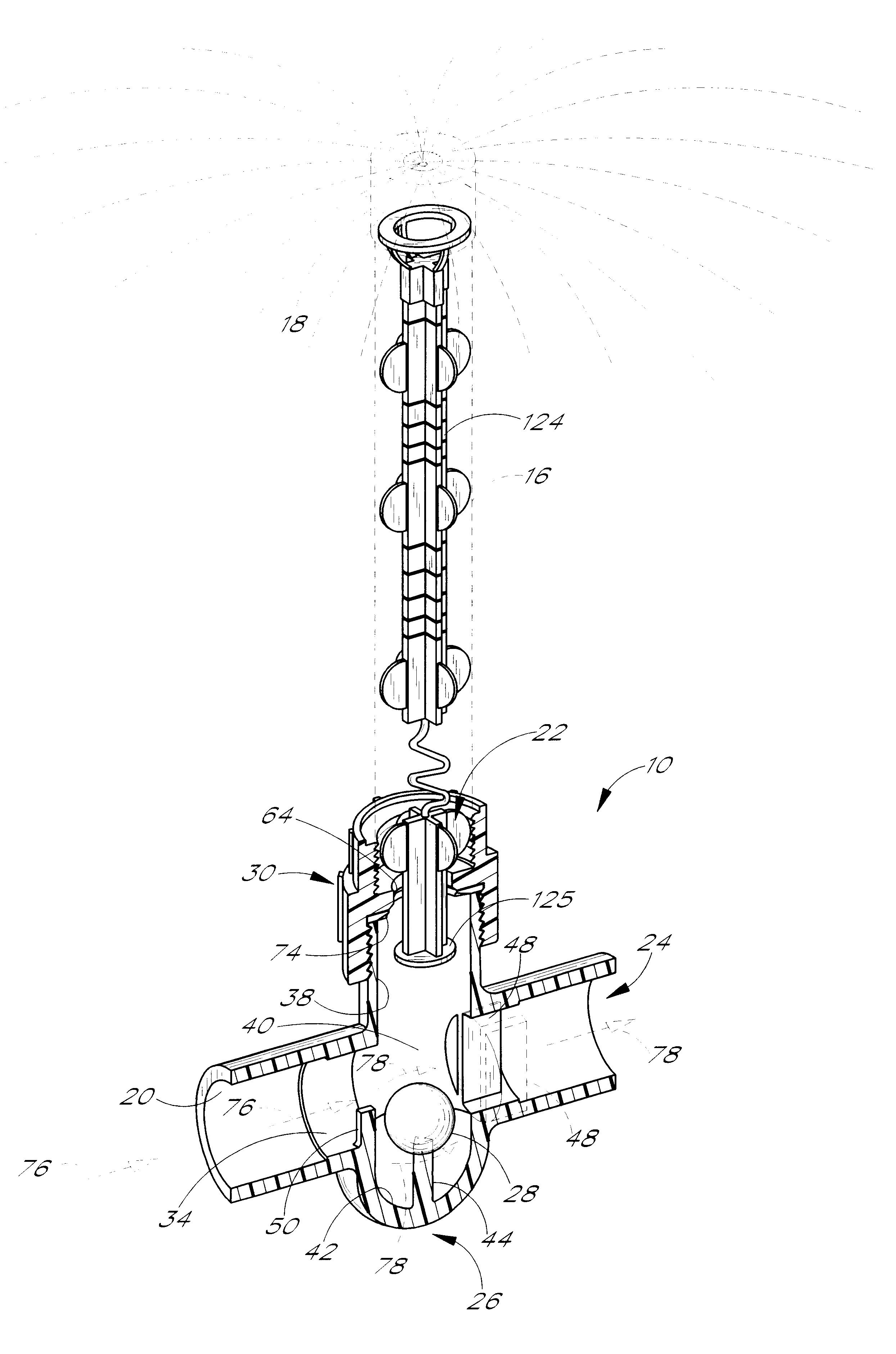
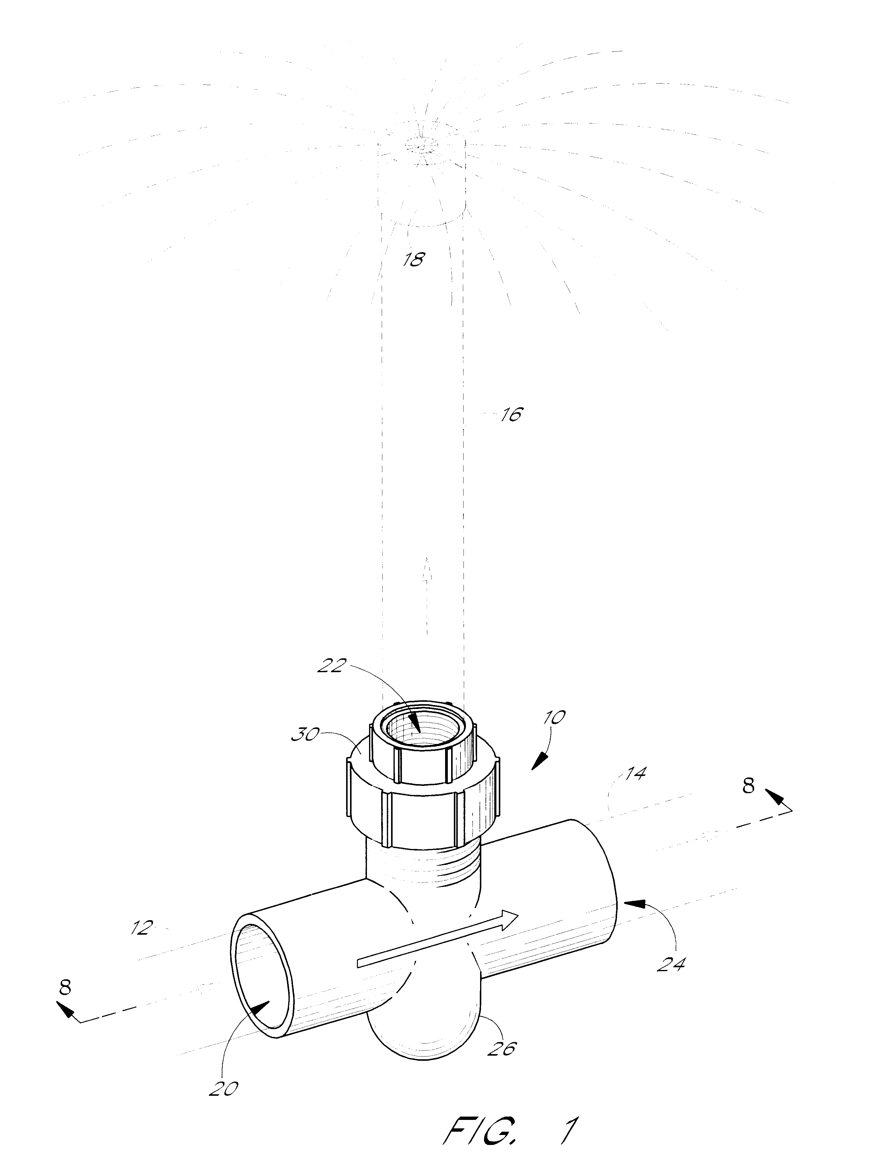
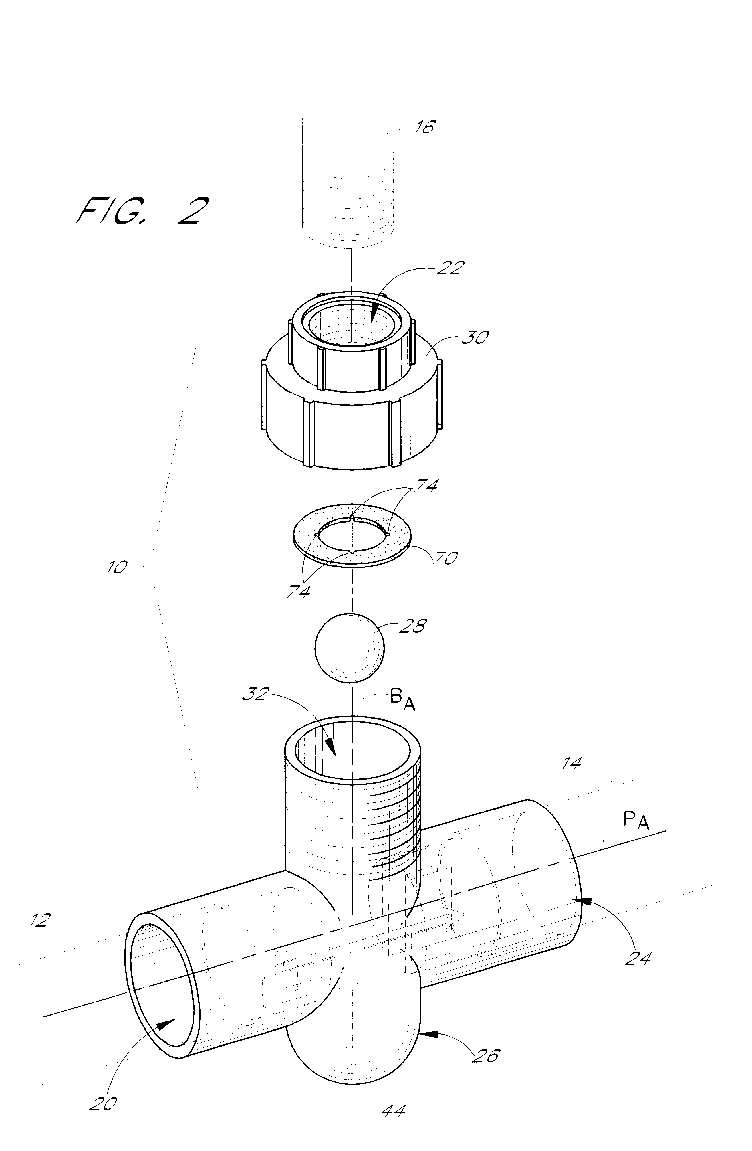
The present invention relates generally to fluid flow control valves for restricting fluid flow rates. Those skilled in the art will readily appreciate that the present invention may have application in a variety of fluid delivery systems where fluid flow through a particular branch of the system should be maintained below a predetermined flow rate or should be arrested if a mechanical failure occurs in a downstream section of the branch. While the following embodiments are described with reference to a riser fluid flow control valve in the context of irrigation systems, it will be understood that the structures, methods and principles described herein are readily applicable to the restriction of fluid flow in other contexts. The irrigation context, therefore, is merely an exemplary field of use.

FIGS. 1-10 illustrate a fluid control valve 10 configured in accordance with a preferred embodiment of the present invention. The valve 10 can be integrated into any of a variety of juncture...


PUM


Abstract

A flow control valve arrests fluid flow from a primary line to a branch line when flow into the branch line exceeds a predetermined flow rate. In one embodiment for use with an irrigation system, the valve includes a T-fitting. The fitting defines a primary passage, which communicates with irrigation pipes, and a branch passage, which communicates with a riser and sprinkler assembly. A valve seat is located within a housing that couples with the fitting. The valve seat is located within the T-fitting when the valve is assembled. The location of the valve seat within the fitting allows the valve to function even when the riser and/or a portion of the housing is sheared off. A stopper selectively engages a valve seat to inhibit water flow through the branch passage when the flow rate through the branch passage exceeds the predetermined flow rate. In one embodiment, a biasing device prevents the stopper from engaging with the valve seat while the predetermined flow rate through the branch passage is momentarily exceeded by transient flow conditions.

Description

BACKGROUND OF THE INVENTION1. Field of the InventionThe present invention relates to a fluid control system, and in particular to a fluid flow control valve. In one application, the fluid flow control valve can check the free flow of water from a broken or damaged riser of an overhead irrigation system.2. Description of Related ArtOverhead irrigation systems often incorporate water spray devices (e.g., sprinkler heads) mounted on risers. A riser supports a sprinkler some distance above the ground, e.g., one to three feet high. At this elevated position, the sprinkler has an enlarged spray pattern and irrigates a larger area than if the sprinkler were positioned closer to the ground. Riser mounted sprinklers also accommodate crops of varying heights.Risers are pipes or conduits, typically made of plastic such as polyvinylchloride ("PVC"), copper or galvanized steel. In many irrigation systems, the riser extends upward from a fitting of the irrigation system, such as from a "T" or an ...

Claims


Application Information

Patent Timeline
Patent Type & Authority Patents(United States)
IPC IPC(8): B05B15/00B05B15/10F16K17/20F16K17/34
CPCB05B15/10F16K17/34B05B15/74Y10T137/1789Y10T137/7849Y10T137/7873
Inventor BROWN, JOSEPH P.GYBEN, CHRISTOPHER J.NORUM, JR., EDWARD M.
Owner WHETSTONE GRP INT
Why Eureka
Try Eureka