
Machine for drilling oil holes in crankshafts

a crankshaft and oil drilling technology, applied in the direction of metal-working holders, supporters, positioning apparatuses, etc., can solve the problems of inability to tackle factors with multi-station transfer units, initial forecasts may be miscalculated, and the demand is not met, so as to reduce the cost of operation, and eliminate the effect of monetary investmen

Inactive Publication Date: 2001-03-20
ETXE TAR SA
View PDF13 Cites 49 Cited by
  • Summary
  • Abstract
  • Description
  • Claims
  • Application Information

AI Technical Summary

Benefits of technology

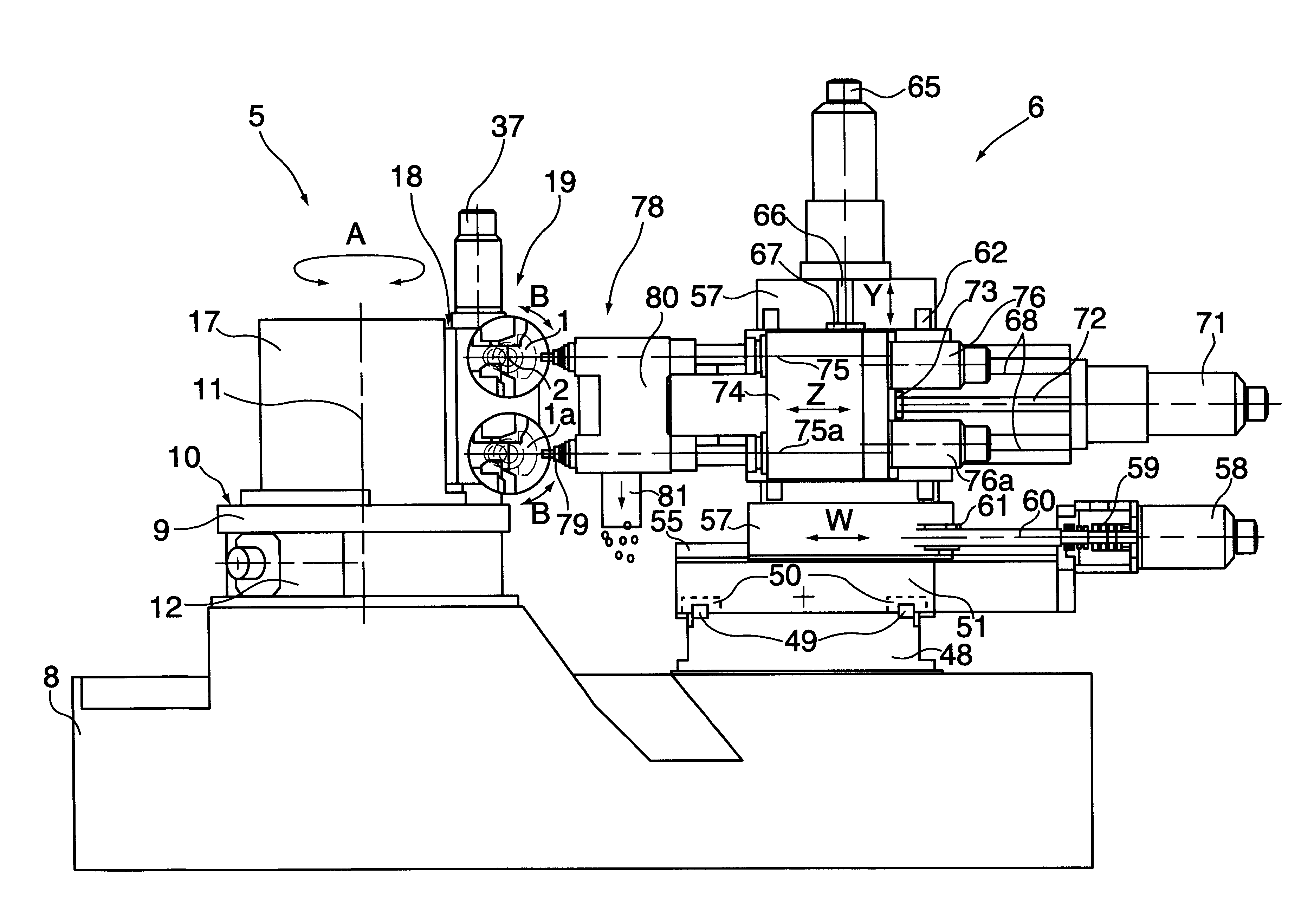
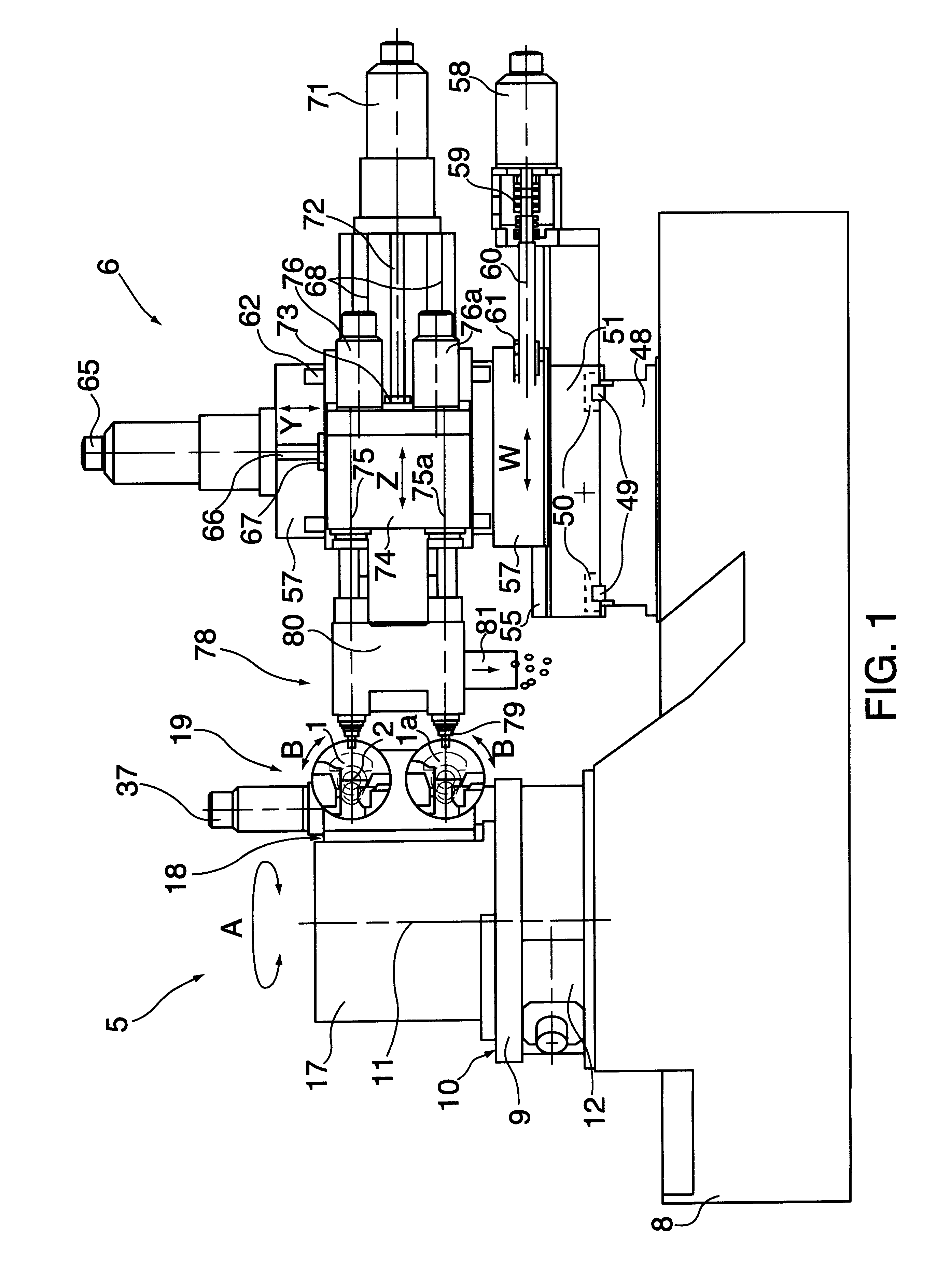
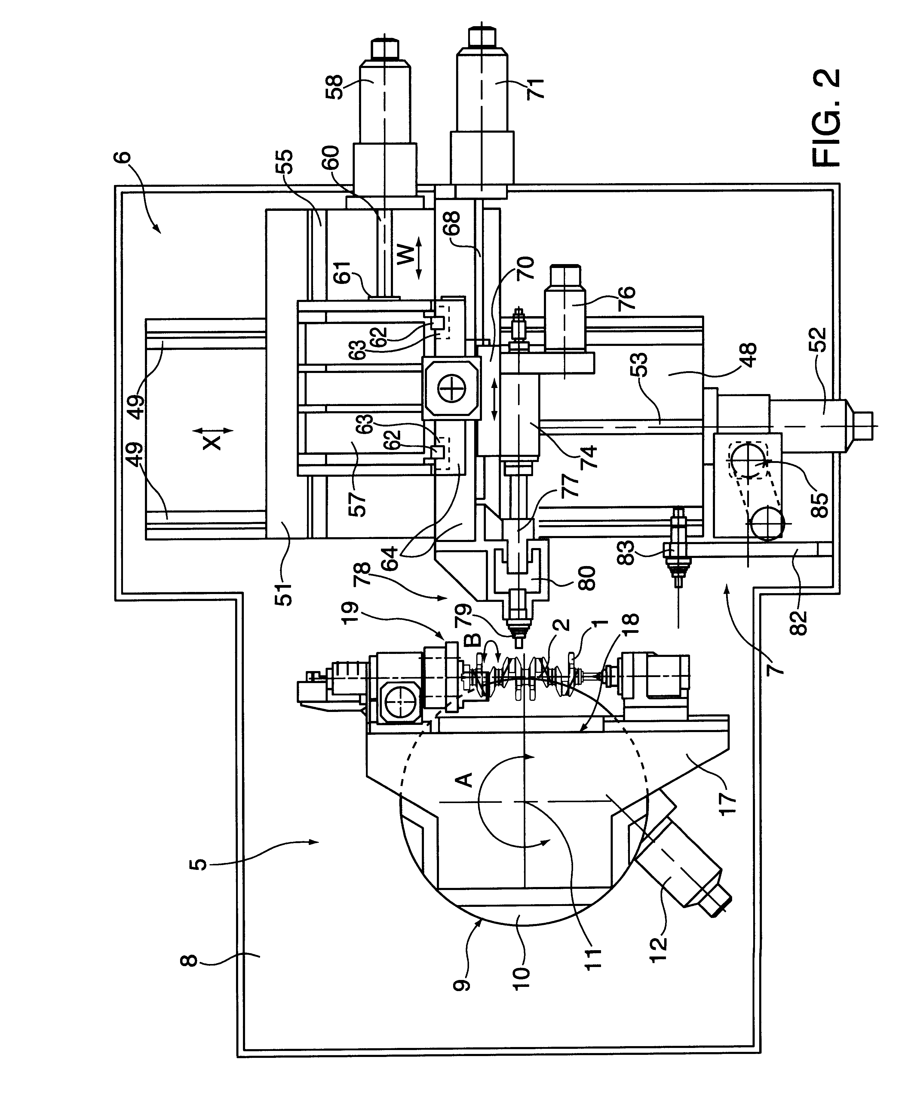
a.sub.1). During the loading / unloading and supporting of the crankshafts and also during all pre-drilling positioning sequences as well as the drilling process, in other words, the whole time the crankshafts are in the machine, their longitudinal axes remain inalterably horizontal (unlike "I A", with its different inclinations to the horizontal). One crankshaft is situated above another, with a suitable distance between them. This is an improvement on the "I A" box-frame with its pivoting, in fact the layout is completely different; the work area is uncluttered, with nothing obstructing the free fall of the chips produced in the drilling process. With no chips piling up on the support elements for the crankshafts, there is no risk of malfunction in automatic loading / unloading.
i.sub.1). One only has to analyse the plans to realise that the direct and convenient accessibility of all parts of the invention, for adjustment, checking and maintenance, has been achieved, thanks to the intelligent layout of all mechanisms / sub-units / units, with the elimination of unnecessary complications and cluttering which cause such problems with "I A".

Problems solved by technology

There is another factor that has been changing in recent years: when a new automobile engine is launched onto the market, there are always doubts about the demand and any initial forecast may be miscalculated, either above or below the mark.
These factors cannot be tackled with multi-station transfer units, because they are not very flexible, nor do they admit progressive investment in line with escalating production brought on by increasing demand, since these are high-cost and high-production machines from the outset.
Furthermore, the diversity of oil-hole placement, explained previously, is not possible in traditional machining centres, with their X, Y and Z axes, at least in mid-high production level.
Also, there is the problem of the additional W axis which is needed to position independently the drill guide bushings, since this fourth axis does not exist in traditional machining centres.
There has been a previous attempt to meet this ambitious objective, but it has not produced the expected results, as it has important drawbacks which in medium-high production are a great inconvenience for an industry as demanding as the automotive industry.
This is a serious drawback, and in subsequent loading / unloading of crankshafts, the piling up of chips will cause malfunctions which are inadmissible in mid-high production.
But with "I A" there now arises another problem and serious at that.
The collecting bin and the outlet pipe together are fairly bulky, and if the chips are of steel, they need to be very bulky, since steel chips are sizeable and difficult to evacuate.
And to avoid this collision, one has to make do with combined collecting bin / outlet pipe apparatuses that are insufficient for their function, giving rise to obstructions in the evacuation of chips, continual stoppages and maintenance requirements that are unacceptable in mid-high production.
This is too much to be hanging free.
In this respect, the inclinations of the crankshafts for holes to be drilled at particular angles to the longitudinal axis of the crankshaft are not precise, as they are affected by the imprecision caused by the zones hanging free, lacking any support.
In addition, the zones hanging free, acting as a counterweight, do not favour precision in inclined positioning power-controlled by the pivoting activator.
The toothed belt, as a result of long-term use, becomes longer and this produces gaps in the gearing with the toothed pulleys, giving rise to defects in the precise circumferential positioning of the crankshafts when turning on their longitudinal axes.
The toothed belts have a limited life and tend to break, requiring their periodical replacement.
This gives rise to maintenance problems, because the transmission is situated in an area with difficult access, as it is surrounded by a large number of mechanisms that get in the way.
This makes maintenance access to these mechanisms difficult.
It also creates an obstruction in the box-frame sub-unit, affecting the elimination of chips (see point a).
There is a further problem.
But there are further problems if there are, for example, three crankshafts, due to the difficulty of belt transmission between one activating axis (the servomotor) and three activated axes in a line.
But if only one or more than two crankshafts are being drilled, as the machining module has to carry one or more than two bushings, the position of the quill with respect to the bushings is not balanced, resulting in problems related to parts hanging free, imbalances and various other complications affecting the stability of the guide bushings during drilling and consequently the precise positioning of the holes.
But this combination of Z moving forward while W moves back requires an interpolation between the two servoactivators to be programmed, an interpolation that complicates programming.
This makes up a bulky and weighty sub-unit with a lot of overhang with respect to the seating of the quill unit, and it does not have the strength and stability needed to support such a sub-unit.
This poses snags and drawbacks of application, even when two crankshafts per cycle are being drilled and the quill unit is between the two bushings.
But these drawbacks are intensified when drilling just one or more than two crankshafts per cycle: the position of the quill unit with respect to the bushings adds further problems (see the first drawback in e).
With all these problems, it is evident that the quill unit is not a good solution for the W axis.
The "I A" machine does not offer these suitable characteristics or additional options.
The loading / unloading station is inflexible and precarious.
It is inflexible for automatic as well as manual loading / unloading.
This involves hazards for the operator in manual loading / unloading if the automatic function has had to be stopped temporarily because of a breakdown or for maintenance.
As these machines are situated in a line with various productive units, attended by a lengthy crankshaft transport and handling system, working simultaneously with a number of arms on their respective production units, if there is a malfunction at one of these stations (for example the grip clamps for handling the crankshafts), then the automatic load / unload function has to be disabled, yet the overall transport and handling system is still functioning at all the stations, and the operator manually loading and unloading at the affected station faces problems and even hazards due to the difficulty of establishing complete safety conditions because the overall system is still operating above.
All this involves considerable bulk and which needs to fit and move in the hazardous gap between the machining module and the crankshaft-carrying sub-unit.
This is a solution that is complicated, a costly investment, awkward and not at all ideal for a flexible machine.
A serious problem in mid-high production is the lack of direct and easy access to all parts of the machine whenever adjustment, checking or maintenance is required.

Method used


Image

  • Machine for drilling oil holes in crankshafts
  • Machine for drilling oil holes in crankshafts
  • Machine for drilling oil holes in crankshafts

Examples


Embodiment Construction

As is shown in the plans and in the description that follows, this invention refers to "a flexible process and machine for drilling oil-holes in different positions in a range of various types of crankshaft".

The crankshaft (1) has a longitudinal axis (2), FIGS. 1, 2 and 6. For functioning in a combustion engine, it needs various different oil-holes, some inclined (3) at different angles, FIG. 7 and others (4) at right angles to the longitudinal axis. These holes have different positions along and around the longitudinal axis (2) and also have different positionings in the circumference described by the crankshaft when it revolves on its longitudinal axis (2). When the shape and / or dimensions of the crankshaft are changed, or when the engine's cylinder capacity is changed, very often it is necessary to modify the longitudinal, transverse (widthways) and circumferential positionings, and also the angling of the oil-holes. There may also be a variation in the number of holes to drill, ...


PUM

PropertyMeasurementUnit
anglesaaaaaaaaaa
lengthsaaaaaaaaaa
flexibleaaaaaaaaaa

Abstract

A machine for drilling oil-holes in crankshafts and the corresponding procedure. It can be used to drill one, two or more crankshafts per cycle. Each crankshaft can revolve on its own axis. The unit described is mounted on a horizontally-faced rotary table with vertical rotating axis, to place the crankshafts at different angles to the Z axis of the machining module, maintaining the horizontal position of the longitudinal axes of the crankshafts. Facing the unit is the machining module, provided with two horizontal spindles, drill tool-holders, with their corresponding guide bushings and parallel to each other, one on top of the other, at the same distance as the two crankshafts. The module has movement in three co-ordinates: axis X (horizontal-transverse), Y (vertical ) and Z (horizontal-presenting tools). A fourth axis W, (with additional module and independent action), moves parallel to Z and carries the guide bushings. It is provided with an automatic changeover, (tool+bushing or just the bushing), incorporating simultaneously the pair of spindles.

Description

This invention relates to a flexible process and machine for drilling oil-holes in different positions in a range of various types of crankshaft, in medium- or high-capacity production, for combustion engines (cars, . . . ).Oil-holes may be situated in various positions lengthways and widthways on the longitudinal axis of a crankshaft, as well as in different positions around the circumference described when turning on this longitudinal axis. They may also be perpendicular or with various angles of inclination with respect to this longitudinal axis of the crankshaft.Until the automotive industry concerned itself with the concept of flexibility, the machining described was undertaken by transfer units (multi-station lines), with each station drilling one of various holes. This solution has been valid in times of few changes in the dimension and shape of crankshafts, when an automobile engine was certain to have an extended life on the market. But now that changes are frequent, both m...

Claims


Application Information

Patent Timeline
Patent Type & Authority Patents(United States)
IPC IPC(8): B23Q1/62B23Q39/00B23Q3/155B23Q39/04B23Q3/157B23B41/00B23B39/00B23B39/16B23Q1/25
CPCB23B39/161B23Q1/626B23Q3/15526B23Q3/15786B23Q39/04B23B41/00Y10T408/03B23B2215/20Y10T408/3811Y10T409/303808Y10T408/93Y10T409/30896Y10T483/1736Y10T483/10Y10T409/305824Y10T483/1748B23Q1/445
Inventor GORROCHATEGUI, GORKA
Owner ETXE TAR SA
Learn More