Trim resistor connector and sensor system

a technology of resistor connector and trim resistor, which is applied in the direction of contact member penetrating/cutting insulation/cable strand, coupling device connection, instruments, etc., can solve the problems of mold tooling cost, limited flexibility and adaptability of current practice,

Inactive Publication Date: 2001-03-27
DELPHI TECH INC
View PDF8 Cites 66 Cited by
  • Summary
  • Abstract
  • Description
  • Claims
  • Application Information

AI Technical Summary

Benefits of technology

Accordingly, among the objects of the present invention are to provide an improved trim resistor connector assembly and improved system coupling of the same that provides a solution to the aforementioned problems and overcomes the aforementioned disadvantages of existing trim resistor constructions employed in conjunction with various automotive sensors in vehicle electronic systems.

Problems solved by technology

This current practice is thus limited in flexibility and adaptability when it is desired to provide resistance trim capability as an add-on to exhaust system sensors in automotive vehicle electronic systems.
Mold tooling costs are also a problem when system design changes are mandated.

Method used


Image

  • Trim resistor connector and sensor system
  • Trim resistor connector and sensor system
  • Trim resistor connector and sensor system

Examples


first embodiment

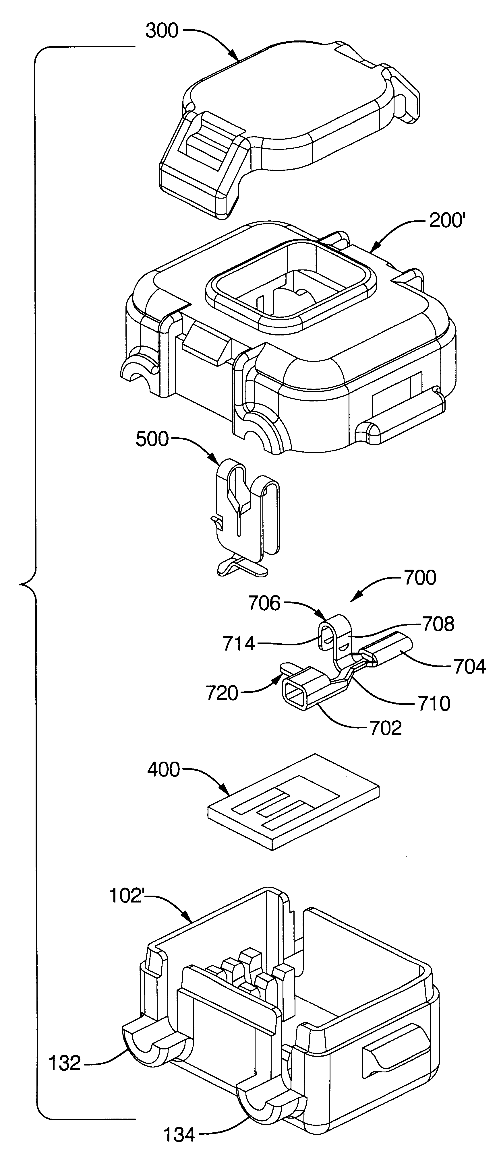
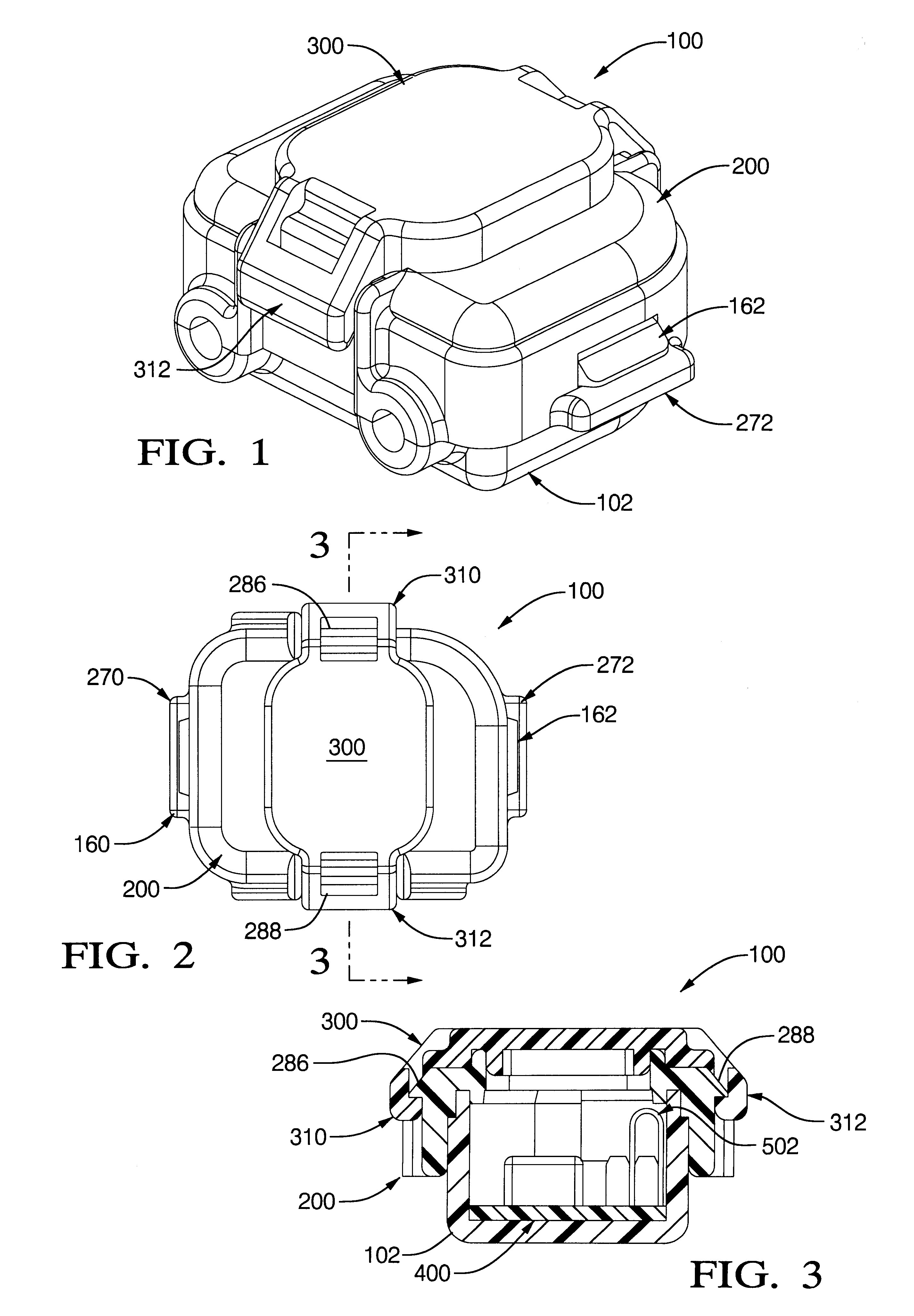
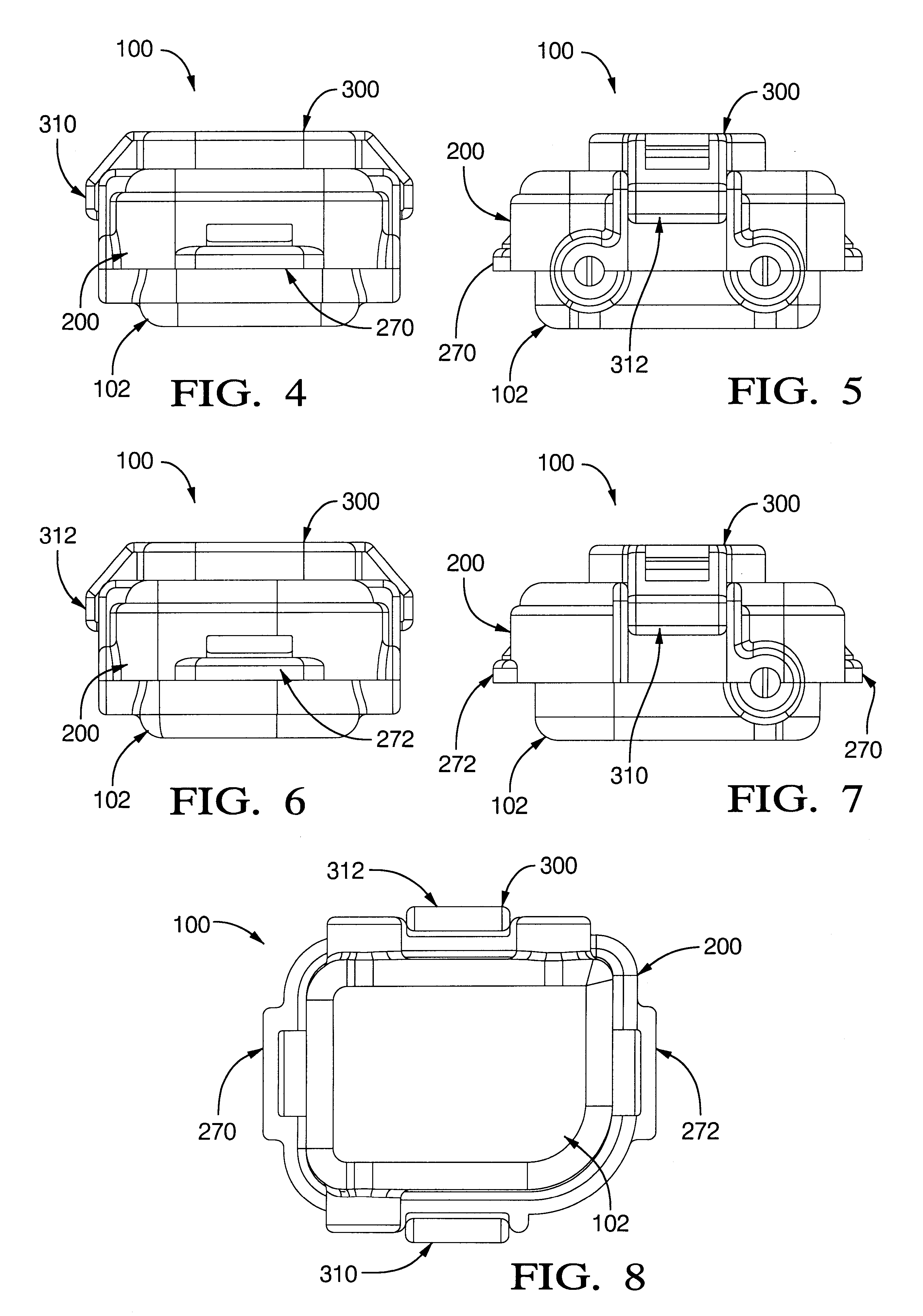
Referring in more detail to the accompanying drawings, the connector assembly of the invention is shown assembled in FIGS. 1 through 8 and in exploded perspective in FIG. 9 and is made up of the following six principal components:

(1) A housing base herein termed the "connector" 102;

(2) A cover 200;

(3) A cap 300;

(4) A conventional trim resistor substrate 400;

(5) A first insulation displacement connector (IDC) terminal 500; and

(6) A second IDC terminal 502.

The housing base part, i.e., connector 102, is shown by itself in FIGS. 12 through 21, these views being to engineering scale and incorporated herein by reference to facilitate making and using the first embodiment of the invention. Connector 102 is preferably an injection molded part made of suitable plastic material having good electrical insulation and heat and moisture resistance properties. It will also be seen from these views that connector 102 has generally an open top cup shape as defined by a bottom wall 120 basically of r...

second embodiment

In the second embodiment connector assembly 600, the connector end of output lead LW.sub.2 (not shown in FIGS. 52-66) is provided with a special crimp-type terminal 700 shown in exploded perspective in FIG. 52, by itself in FIGS. 53-58 and in assembly with a modified connector 102' of connector assembly 500 in FIGS. 59 and 60. Connector 700 is generally of the crimp-on type made by progressive die-stamping and bending for clasping the end of an insulated lead wire having the metallic conductor core stripped of insulation for a short distance at its free end. Preferably the lead wire is inserted bare-wire-end first through the larger diameter tunnel 702 formed at one end of terminal 700 until the bared core free end is received within a narrower diameter tunnel 704 at the opposite axial end of terminal 700. Tunnel 702 is the mechanically crimped to squash onto and grip the insulated portion of the lead wire, and likewise the smaller tunnel 704 is mechanically crimped to squash onto a...


PUM

PropertyMeasurementUnit
anglesaaaaaaaaaa
resistive conductiveaaaaaaaaaa
resistanceaaaaaaaaaa

Abstract

An improved IDC trim resistor connector assembly made up of a generally open top cup shape connector with side wall slots and an interior first array of terminal posts arranged for passage therethrough of a first lead wire of sensor circuitry. A first stamped metal IDC terminal is push-on mounted on the terminal posts for IDC cradling and electrically and mechanically receiving and connecting to the first lead wire. A conventional trim resistor substrate is loose mounted but accurately positioned on the connector bottom wall and has an "E" pattern of resistive material adapted for center leg laser trimming to calibrate the associated sensor circuitry. A first IDC terminal spring leg overlap contacts one side leg of the trim resistor E-pattern and thereby spring clamps the resistor substrate. A cover is snap-latch mounted on the connector and has an access opening to enable laser trimming of the trim resistor after cover installation. One end of a second lead wire is received in a second IDC metal terminal in turn mounted on a second array of connector-interior terminal posts and also having a spring leg overlap electrically contacting and clamping the other E-pattern side leg. Spring barbs on the terminals anchor the same once fully inserted downwardly onto the terminal posts. Connector locking tangs and cover locking ears provide snap-on retention of the cover on the connector, and press-in/keeper internal cover projections cause push-down assembly of the lead wires as the cover is latched onto the connector. Cover locking tangs and cap latching ears provide snap-together locking of a cap on the cover when the cap is pushed down on the cover to seal the access opening after completion of laser trimming and in-filling of the covered container with sealant. In a second embodiment a crimp-type terminal, also provided with a spring clamping leg, is fastened to the second lead wire and has a barbed mounting strap clasping a modified second terminal post array when fully installed thereon.

Description

The present invention relates to calibration of automotive sensor circuitry, and more particularly to a trim resistor connector assembly for mechanical and electrical coupling into the output circuitry of a sensor element provided in an automotive electronic control system.With the steady growth in recent years of vehicle electronic systems, the number of sensors used in automobiles has also risen dramatically. Current vehicles can contain forty to fifty of such sensors. Among the types of sensors commonly provided are pressure sensors in the vehicle fuel systems, air bag sensors, over-current and over temperature-protection sensors, oxygen sensors for exhaust gas systems, catalyst temperature sensor, etc. With most if not all of such sensors, signal conditioning will be necessary for most sensor elements. Raw sensors exhibit some level of offset voltage in output signal level when no stimulus is applied to the sensor. Typically, a potentiometer or a trim resistor branch circuit tha...

Claims


Application Information

Patent Timeline
Patent Type & Authority Patents(United States)
IPC IPC(8): G01L9/00H01C10/46H01C10/00H01C17/22H01C17/242H01R13/66H01R4/24H01R13/502H01R13/52H01R13/504
CPCG01L19/0084H01C10/46H01C17/242H01R13/6683H01R4/2433H01R4/2462H01R13/5045H01R13/5213
Inventor STEIN, SR., WILLIAM L.LOUTZENHISER, RICKMCCALL, MARK D.
Owner DELPHI TECH INC
Why Eureka
Try Eureka