Automatic transmission with dual gain multi-disk friction device

a multi-disk, automatic transmission technology, applied in the direction of fluid couplings, fluid actuated brakes, couplings, etc., can solve the problems of unable to provide an easily assembled friction disc coupling, accompanied by undesirable harshness, and failure to engage an underdrive speed ratio band brak

Inactive Publication Date: 2001-05-08
BORGWARNER INC
View PDF9 Cites 45 Cited by
  • Summary
  • Abstract
  • Description
  • Claims
  • Application Information

AI Technical Summary

Problems solved by technology

In certain prior art mechanisms the engagement of an underdrive speed ratio band brake is accompanied by an undesirable harshness due to the sudden application of friction braking torque.
While suitable for their intend

Method used


Image

  • Automatic transmission with dual gain multi-disk friction device
  • Automatic transmission with dual gain multi-disk friction device
  • Automatic transmission with dual gain multi-disk friction device

Examples


Embodiment Construction

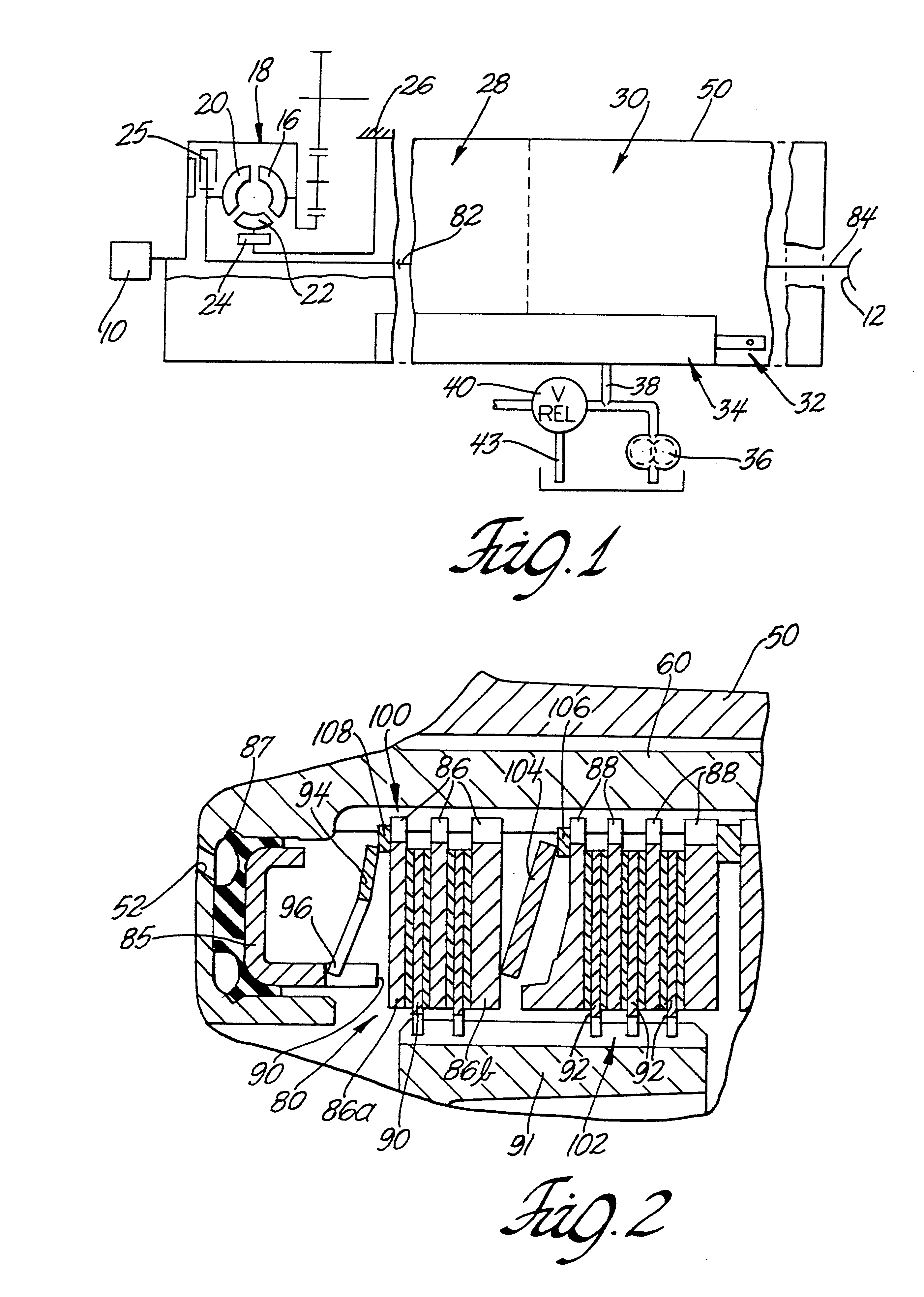
Numeral 10 designates a prime mover such as an internal combustion engine in an automotive vehicle driveline. Numeral 12 designates the vehicle traction wheels, which are connected through a suitable differential-and-axle mechanism to a driveshaft, which is connected in turn to the driven shaft 14 of the transmission. The crankshaft of engine 10 is connected to impeller 16 of hydrokinetic torque converter 18. Impeller 16 includes a shell, which encloses the bladed members of the converter, the latter comprising impeller 16, turbine 20 and stator 22. The bladed converter members are arranged in toroidal fluid flow relationship in the usual fashion. Stator 22 is a dapted to rotate in the direction of rotation of the impeller, but it is braked against rotation in the opposite direction by overrunning brake 24 supported by stationary stator sleeve shaft 26.

The torque converter includes a lock-up clutch 25 that is selectively controlled during speed changes to be disengaged whereby the t...


PUM


Abstract

A fluid pressure operated friction coupling comprising a multiple friction disc assembly having a single piston actuator and having first and second springs operatively configured and arranged in response to pressurization of the piston actuator to selectively engage first and second sets plates and friction components for varying the gain of the coupling.

Description

1. Field of the InventionThe present invention relates to friction devices such as clutch or brake assemblies for use in transmissions, differentials or brake systems and more particularly to such devices having a piston actuated clutch or brake pack including separator plates and friction discs.2. Description of the Prior ArtThe transmission mechanism described here includes a hydrokinetic torque converter having a bladed impeller driven by an internal combustion engine for an automotive vehicle. The converter includes also a bladed turbine and a bladed stator situated in toroidal fluid flow relationship with respect to the impeller. The turbine is connected to torque input elements of a multi-speed ratio planetary gear system. The output portion of the gear system is connected to a transmission tailshaft, which in turn is connected to the vehicle traction wheels through a driveshaft and differential-and-axle assembly.The reaction element for the gear system is adapted to be anchor...

Claims


Application Information

Patent Timeline
IPC IPC(8): F16D25/0638F16D25/06F16D25/10F16D25/00F16D65/14F16D55/24F16D55/40F16D55/00F16D25/12F16F1/18F16H57/02
CPCF16D25/0638F16D25/10F16D55/40F16D2055/0058F16D2121/02F16D2125/06F16D2127/007F16D21/06
Inventor BRAFORD, JR., THOMAS E.
Owner BORGWARNER INC
Why Eureka
Try Eureka