Transfer impedance measurement instrument system

a technology of transfer impedance and measurement instrument, which is applied in the direction of instruments, mechanical roughness/irregularity measurement, mechanical measuring arrangement, etc., can solve the problems of high-value electronics, human life is particularly vulnerable to the effects of lightning, and it is not known how most buildings will fare in protecting their contents

Inactive Publication Date: 2001-05-08
BOLT
View PDF9 Cites 40 Cited by
  • Summary
  • Abstract
  • Description
  • Claims
  • Application Information

AI Technical Summary

Problems solved by technology

Buildings of all types and their contents are vulnerable to the ever-present threat of lightning.
High-value electronics, computers, communications systems, explosives, and human life are all particularly vulnerable to the effects of lightning.
While many buildings have a metallic sub-structure that provides some protection against the effects of lightning, it is currently unknown how most buildings will fare in protecting their contents when struck.
If not well bonded, however, the shelter is an ineffective shield, and significant electric fields can be transmitted into the shelter.
Second, the conventional lightning protection systems appliqued to shelters are ineffective and conduct only a small part

Method used


Image

  • Transfer impedance measurement instrument system
  • Transfer impedance measurement instrument system
  • Transfer impedance measurement instrument system

Examples


example

Synchronous Detection as Implemented in TIMIS

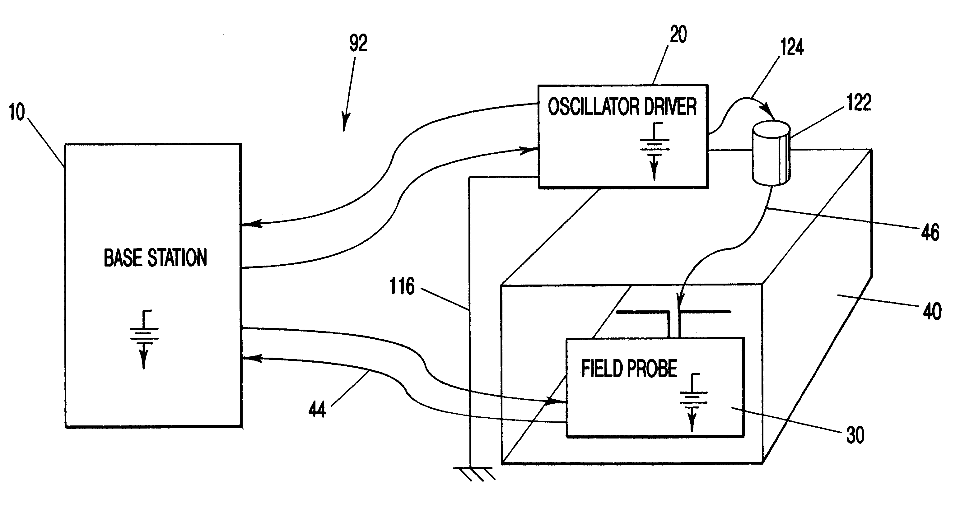
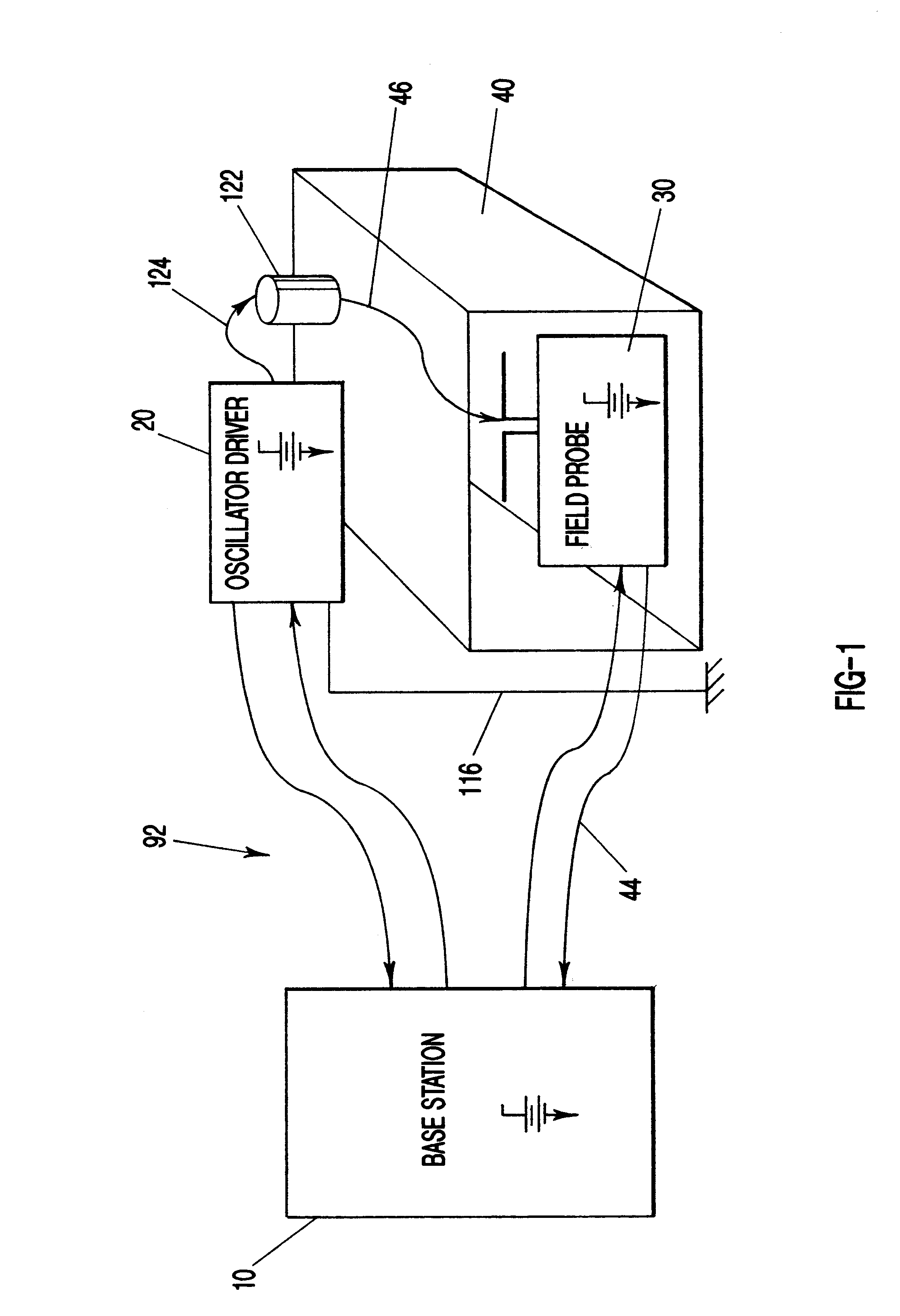
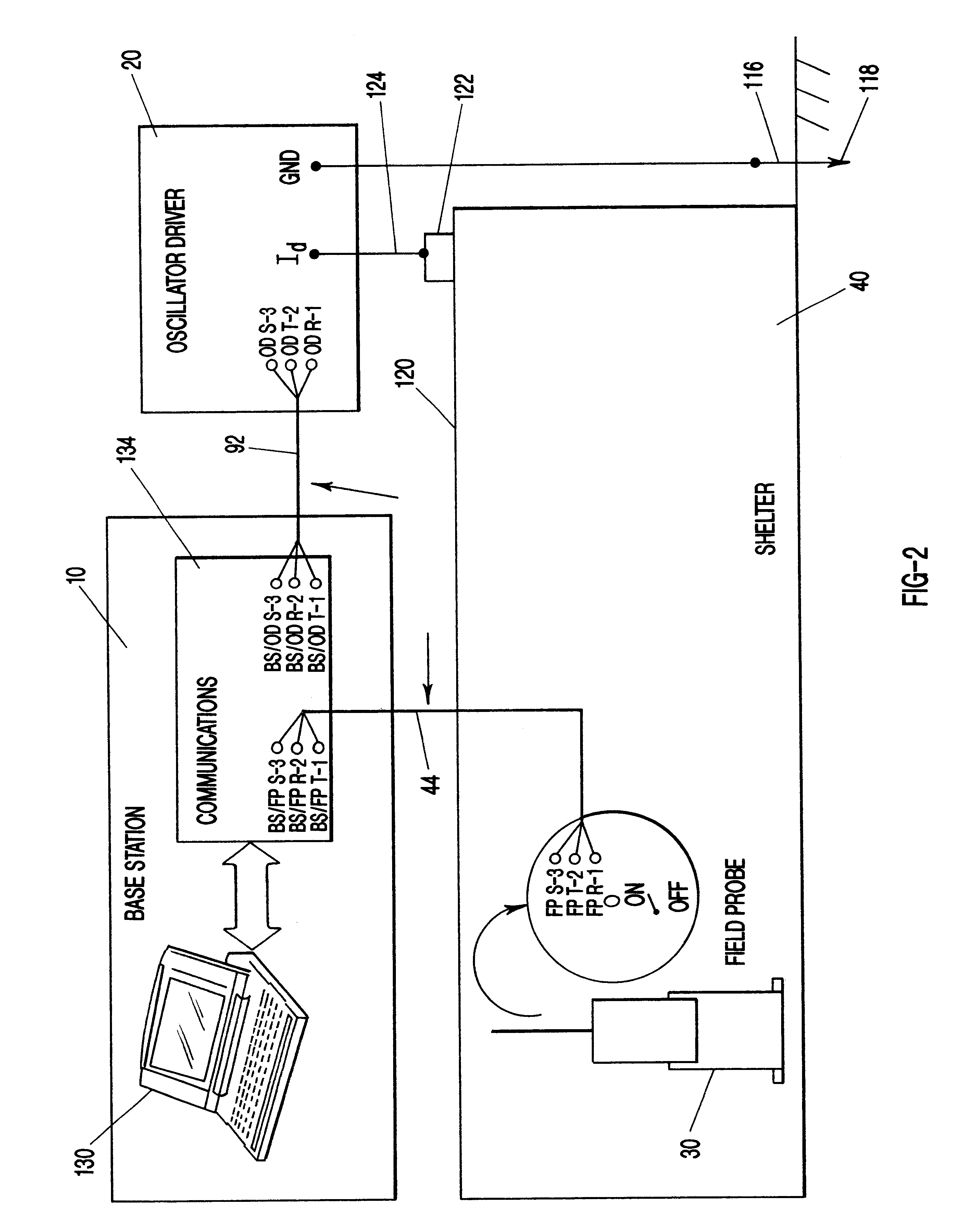
This discussion considers the processing of the various TIMIS measurement information to determine the received electric field voltage at the field probe and subsequently to determine the transfer impedance function. This processing occurs both in hardware and firmware at the field probe and oscillator driver, and in the base station software.

The signal S.sub.1 is the output of preamplifier 50 (of FIG. 5), amplified V.sub.ef, in response to the structure excitation by I.sub.d, the drive current. Upper-case signal names in this discussion indicate the frequency domain; lower-case signal names indicate the time domain.

s.sub.1 (t)=AV.sub.ef (t)=Asin (2.pi.ft+.phi.)=Asin (u+.phi.)

where:

u=2 .pi.ft

f--frequency, t--time

V.sub.ef (t)=A.sub.p sin (2 .pi.ft+.phi..sub.p)

V.sub.ef (t), V.sub.ef --electric field voltage at the probe

A=G.sub.a G.sub.pa A.sub.p

A.sub.p --amplitude of the electric field voltage

.phi..sub.p --phase of the electric field voltag...


PUM


Abstract

An apparatus and method for measuring the transfer impedance of a structure. Oscillator driver 20 produces a small electrical drive signal into structure 40. Field probe 30 detects the electric field produced by the drive signal and is comprised of a skinny half-dipole and fat half-dipole antenna. Fat half-dipole 34 encloses synchronous detection circuitry. Power supplies are isolated for all components. Base station 10 communicates with oscillator driver 20 and field probe 30 via wireless links 92 and 44 to control the drive signal, the synchronous detection, and to determine the transfer impedance.

Description

1. Field of the Invention (Technical Field)The present invention relates to measuring transfer impedance, particularly the transfer impedance of structures, to assess vulnerability to lightning.2. Background ArtBuildings of all types and their contents are vulnerable to the ever-present threat of lightning. High-value electronics, computers, communications systems, explosives, and human life are all particularly vulnerable to the effects of lightning. While many buildings have a metallic sub-structure that provides some protection against the effects of lightning, it is currently unknown how most buildings will fare in protecting their contents when struck. Hospitals, banks, bunkers for nuclear weapons, shelters for explosives, and buildings that house flight-control systems can all benefit from an analysis of their susceptibility to the effects of a lightning strike.Past experimental and analytical work to assess the ability of typical explosives shelter to protect their contents f...

Claims


Application Information

Patent Timeline
IPC IPC(8): G01R15/00G06F19/00G01F19/00G01R31/00H02G
CPCG01R29/0842G01R31/001
Inventor HARRIS, CLIFF A.LOVE, JERRY T.
Owner BOLT
Why Eureka
Try Eureka