
Oxygen-gaseous forehearth burner for air-fuel and oxy-fuel forehearth burner block geometries

a technology of air-fuel and oxy-gas, which is applied in the field of forehearth systems, can solve the problems of poor fuel efficiency, limited turn down ratio, and high process temperature of glass melting furnaces, and achieves the effects of low production efficiency, and low heat dissipation efficiency

Inactive Publication Date: 2001-05-22
ECLIPSE
View PDF14 Cites 25 Cited by
  • Summary
  • Abstract
  • Description
  • Claims
  • Application Information

AI Technical Summary

Benefits of technology

It is yet another object of this invention to provide a forehearth burner system which is fuel efficient.
It is still another object of this invention to provide a forehearth system for a glass melting furnace having improved forehearth temperature control.

Problems solved by technology

Glass melting furnaces require extremely high process temperatures for glass production.
Numerous problems exist for traditional forehearth firing systems which employ premixed air-fuel burners for heating the flowing gas, including poor fuel efficiency, little or no flame luminosity, very limited turn down ratio, a high volume of combustion gases and associated emissions within and outside of the glass plant, a generally high noise level due to the air-gas combustion system and, finally, the inability to provide precise temperature control of the glass, as small as 1.degree. or 2.degree. F. due to the significant variations in atmospheric air used by air-gas firing systems.
This recirculation accelerates burner tip corrosion and plugging, which leads to premature failure of the burner.
In addition, because the gas and oxygen flow streams are parallel to each other upon exit from the burner, mixing is delayed, resulting in a long flame which can impinge on the opposing wall of a narrow forehearth.

Method used


Image

  • Oxygen-gaseous forehearth burner for air-fuel and oxy-fuel forehearth burner block geometries
  • Oxygen-gaseous forehearth burner for air-fuel and oxy-fuel forehearth burner block geometries
  • Oxygen-gaseous forehearth burner for air-fuel and oxy-fuel forehearth burner block geometries

Examples


Embodiment Construction

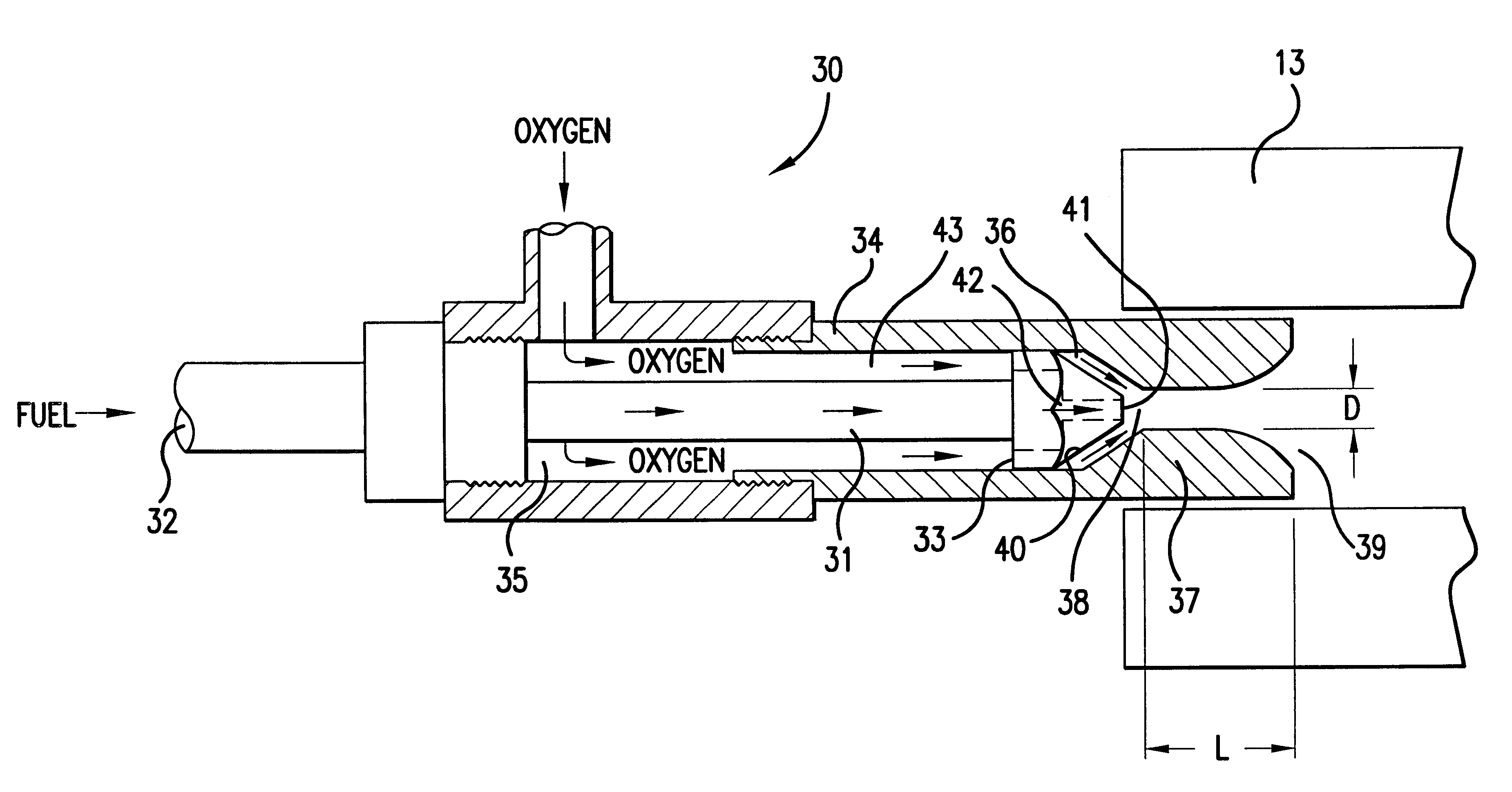
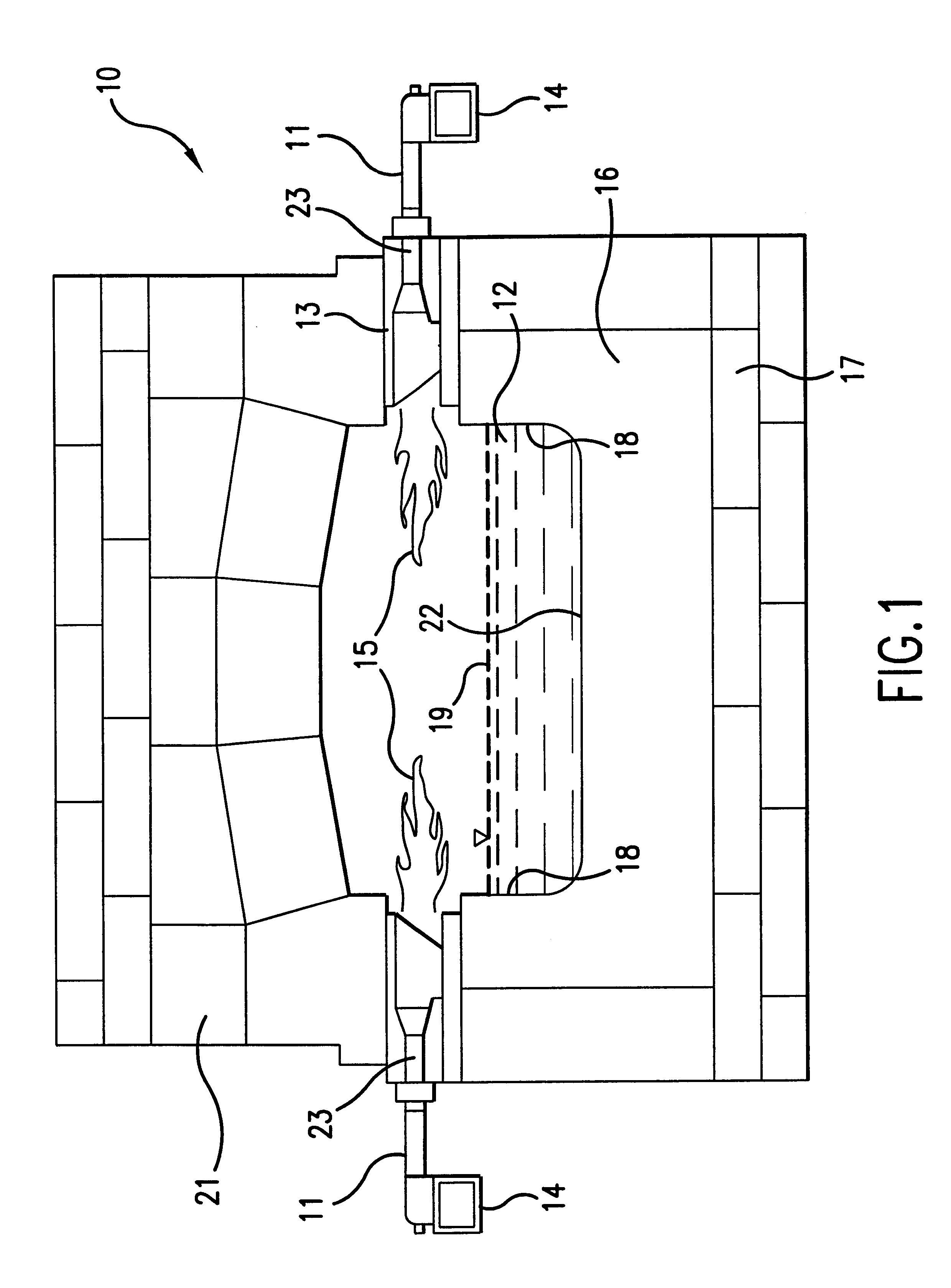
FIG. 1 is a cross-sectional view of a typical forehearth 10 for a glass melting furnace comprising longitudinally extending trough 16 supporting a bed of molten glass 12 therein. Trough 16 is supported by substructure 17. Trough 16 has a substantially wide floor portion 22 and oppositely-disposed inner sidewall surfaces 18 which project above the top level or upper surface 19 of molten glass 12. Above trough 16, and spanning the trough width, is roof structure 21, typically formed in a building block arrangement using solid refractory and insulating block sections having complementary registering surfaces between adjacent sections which stack and unite to form the whole.

Along the flat top surface of each long side of trough 16 are burner blocks 13. Burner blocks 13 rest upon both trough 16 respective top wall surfaces and the respective top wall surfaces of substructure 17. Roof structure 21, along with burner blocks 13, define a longitudinally-extending space or tunnel above top su...


PUM

PropertyMeasurementUnit
Temperatureaaaaaaaaaa
Lengthaaaaaaaaaa
Diameteraaaaaaaaaa

Abstract

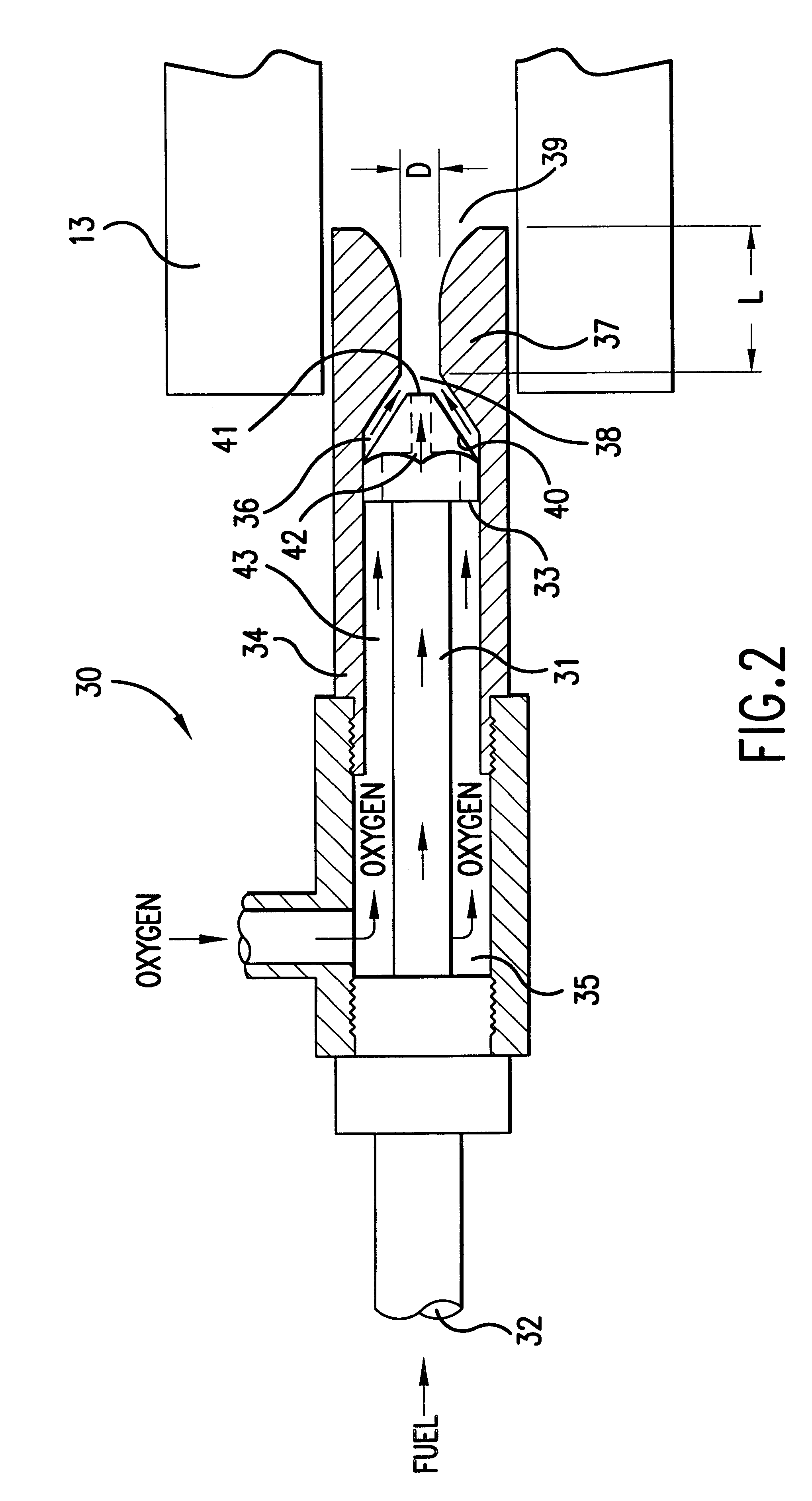
An oxy-gaseous fuel burner for a forehearth system having an oxygen conduit, a fuel conduit disposed concentrically within the oxygen conduit and forming an annulus between the fuel conduit and the oxygen conduit, a precombustor conduit disposed at the oxygen outlet end of the oxygen conduit, and a fuel tip disposed at the fuel outlet end of the fuel conduit. The outlet of the fuel tip is disposed at or upstream of the inlet to the precombustor conduit.

Description

1. Field of the InventionThis invention relates to forehearth systems for conditioning molten glass from a glass melter and rendering it suitable for subsequent processing, such as forming it into a desired shape. More particularly, this invention relates to burner systems suitable for use in forehearth systems, and in particular, forehearth systems employing air-fuel and oxy-fuel forehearth burner block geometries.2. Description of Prior ArtGlass melting furnaces require extremely high process temperatures for glass production. As a result, furnace flame temperatures and, thus, NO.sub.x generation, are high. As a result of the 1990 Clean Air Act, many regional municipalities now impose NO.sub.x emission limits on glass furnaces.Throughout all segments of the glass industry, glass manufacturers have been adopting oxygen-fuel technologies to meet the increasingly stringent NO.sub.x emission limits. Substituting oxygen for air in the combustion process reduces NO.sub.x emissions and y...

Claims


Application Information

Patent Timeline
IPC IPC(8): C03B7/00C03B7/06C03B5/00C03B5/235F23D14/22F23D14/32
CPCC03B5/2353C03B7/065F23D14/22F23D14/32F23M2900/05021Y02E20/344Y02E20/34Y02P40/50
Inventor ANDERSON, SCOTTNITZMAN, JACK L.MOHR, PATRICK J.
Owner ECLIPSE
Learn More