
Apparatus and method for a spray dryer

a dryer and spray technology, applied in drying machines, lighting and heating apparatus, furnaces, etc., can solve the problems of affecting the drying effect,

Inactive Publication Date: 2001-05-29
HENKEL KGAA +1
View PDF10 Cites 23 Cited by
  • Summary
  • Abstract
  • Description
  • Claims
  • Application Information

AI Technical Summary

Benefits of technology

The particles adhering to the inner walls of the spray dryer according to the invention are deposited onto the air-permeable textile which can be cleaned simply and effectively from the back by exposure to a pulse of the compressed gas. When cleaned in this way, the textile expands and adhering particles fly off and are blown into the interior of the drying chamber. There is no longer any need to interrupt the operation of the dryer to clean the walls.
Another advantage lies in the increased performance of the spray dryer according to the invention because the product contains fewer agglomerates which, hitherto, would have been removed as oversize particles by sieving. The absence of deposits according to the invention reduces the risk of fire and allows higher temperatures for the hot gas so that the performance of the spray dryer can be increased.
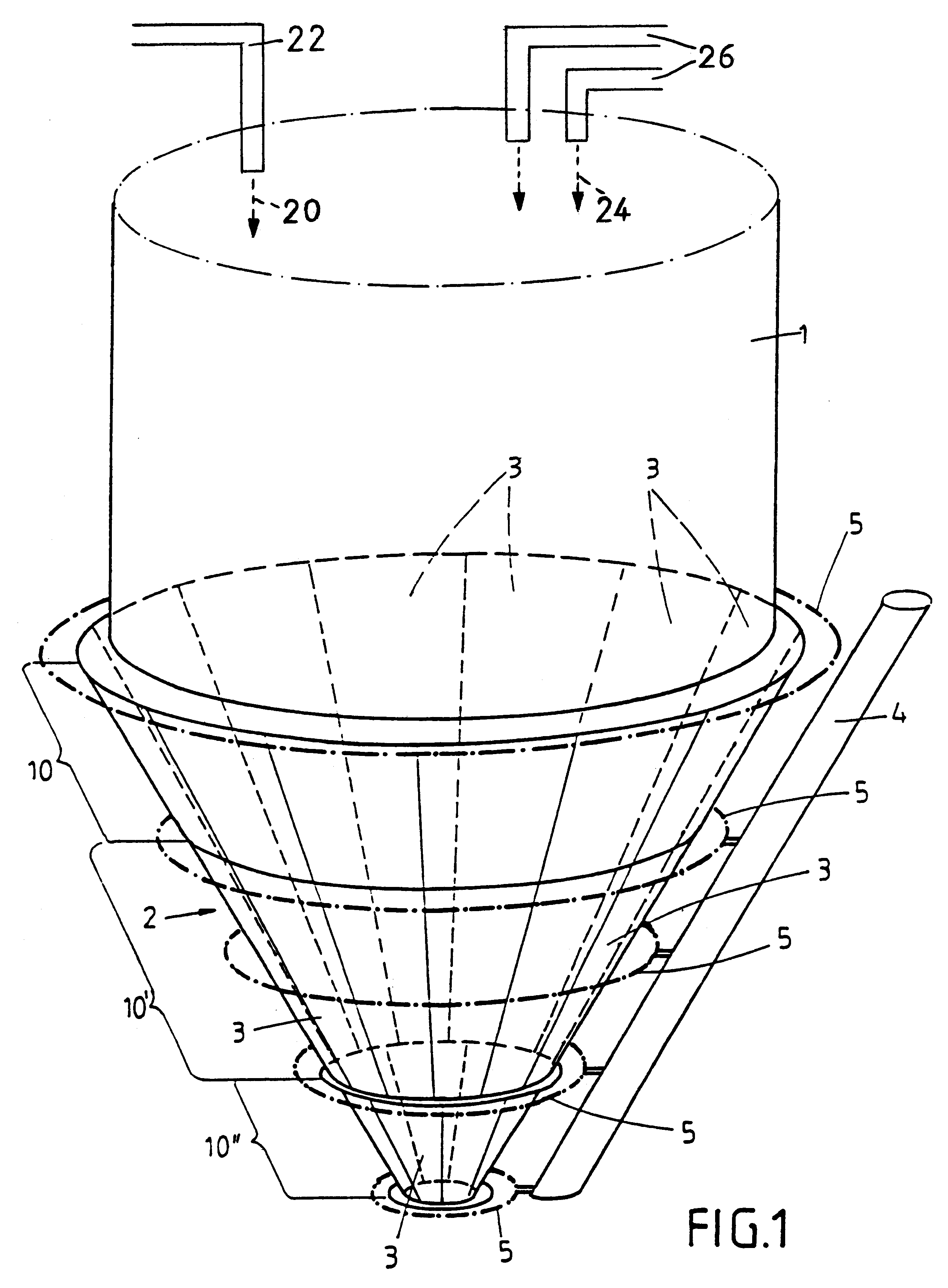
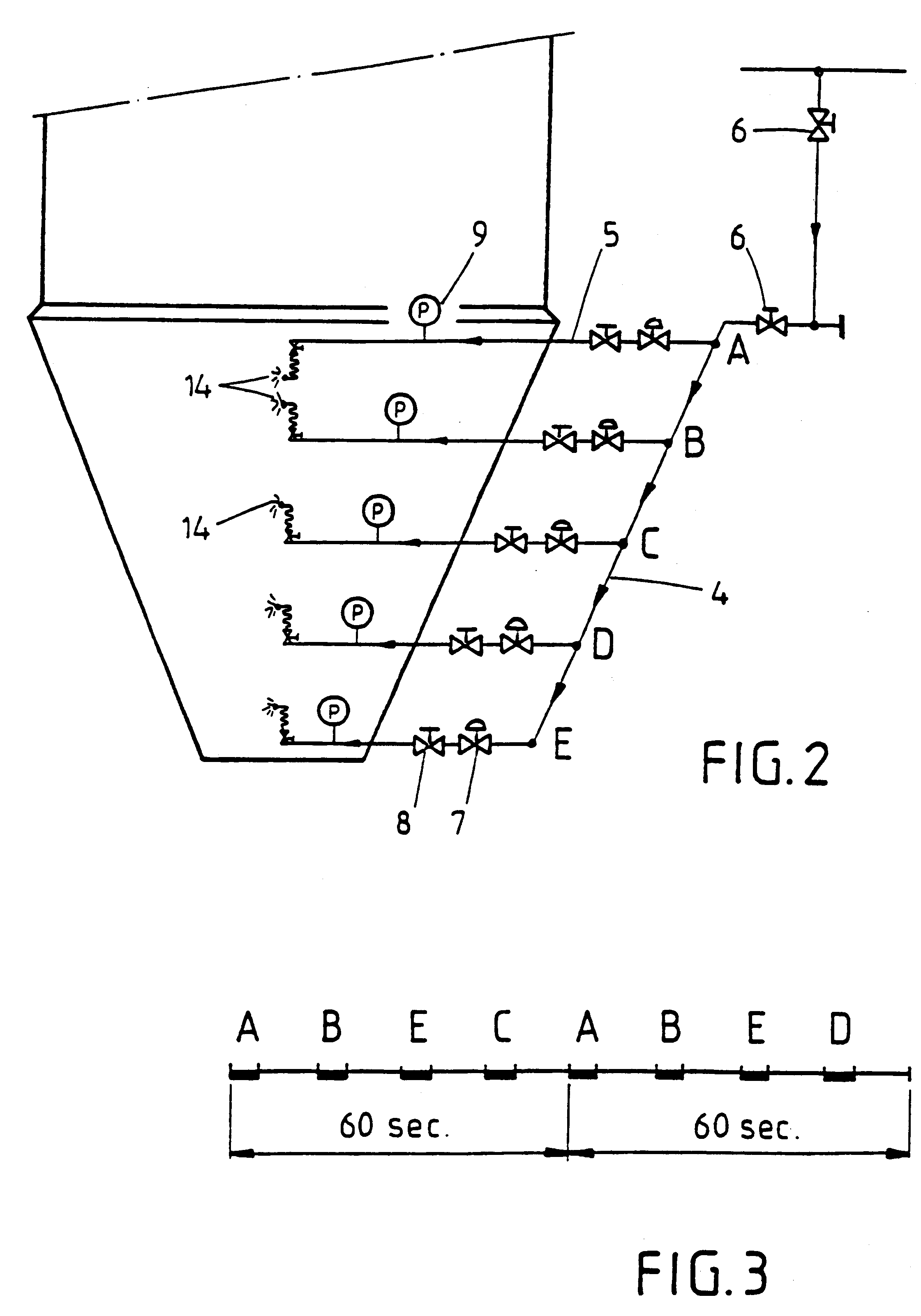
In another preferred embodiment of the invention, at least two outlets for the gas are associated with each textile, being arranged in opposite regions thereof, more particularly in the upper and lower regions thereof. In this way, each textile can be alternately exposed to pulses of the compressed gas from different directions so that the textile is alternately brought into one shape or the other and layers of dried product are prevented from forming locally on the textile. Even if not all parts of the textile are sufficiently moved by the individual pulse of compressed air to remove adhering product, substantially complete cleaning of the textile can be achieved in this way.
In one particularly advantageous embodiment of the invention, the outlets are supplied with compressed gas by annular, substantially horizontally extending gas distribution lines which are designed to be individually actuated. This guarantees an adequate volume of gas each time the particular textile receives a pulse of compressed gas.

Problems solved by technology

On the other hand, the material to be dried generally contains a large percentage of organic ingredients, more particularly surfactants, which are not only temperature-sensitive, they also tend to carbonize and self-ignite at the high temperatures prevailing in the spray dryer if the product remains in the drying chamber for longer than a few seconds.
Unfortunately, some of the material to be spray-dried is inevitably deposited onto the inner walls of the drying chamber where it gradually heats up, dries out completely and, after a certain time, becomes so hard that it is extremely difficult to remove.
These deposits are formed in particular in the production of detergents / cleaners because the only partly dried-on particles, which are rich in surfactants, have a very tacky surface.
In addition, black product particles are formed by carbonization and contaminate the tower powder so that it no longer meets consumer quality requirements.
The problems mentioned above occur to a greater extent with modern detergent formulations which contain particularly large amounts of surfactants.
As a result, the performance of the spray dryer diminishes.
The inclination of the inner walls in this cone leads to increased deposits which, moreover, become particularly hot in this region because the hot drying gas enters the drying chamber in the vicinity of the tower cone.
Although the deposits could conceivably be removed by externally mounted knockers, the resulting deformation of the tower cone would result in damage to the surface and in unevenness in the inner wall which in turn would result in increased deposits.
Other disadvantages include the noise generated, the uncontrolled cleaning and the difficulties involved in removing particularly hard deposits.
In addition, the operational interruptions for cleaning the inner walls of the drying chamber would only be necessary at very much longer time intervals.

Method used


Image

  • Apparatus and method for a spray dryer
  • Apparatus and method for a spray dryer
  • Apparatus and method for a spray dryer

Examples


Embodiment Construction

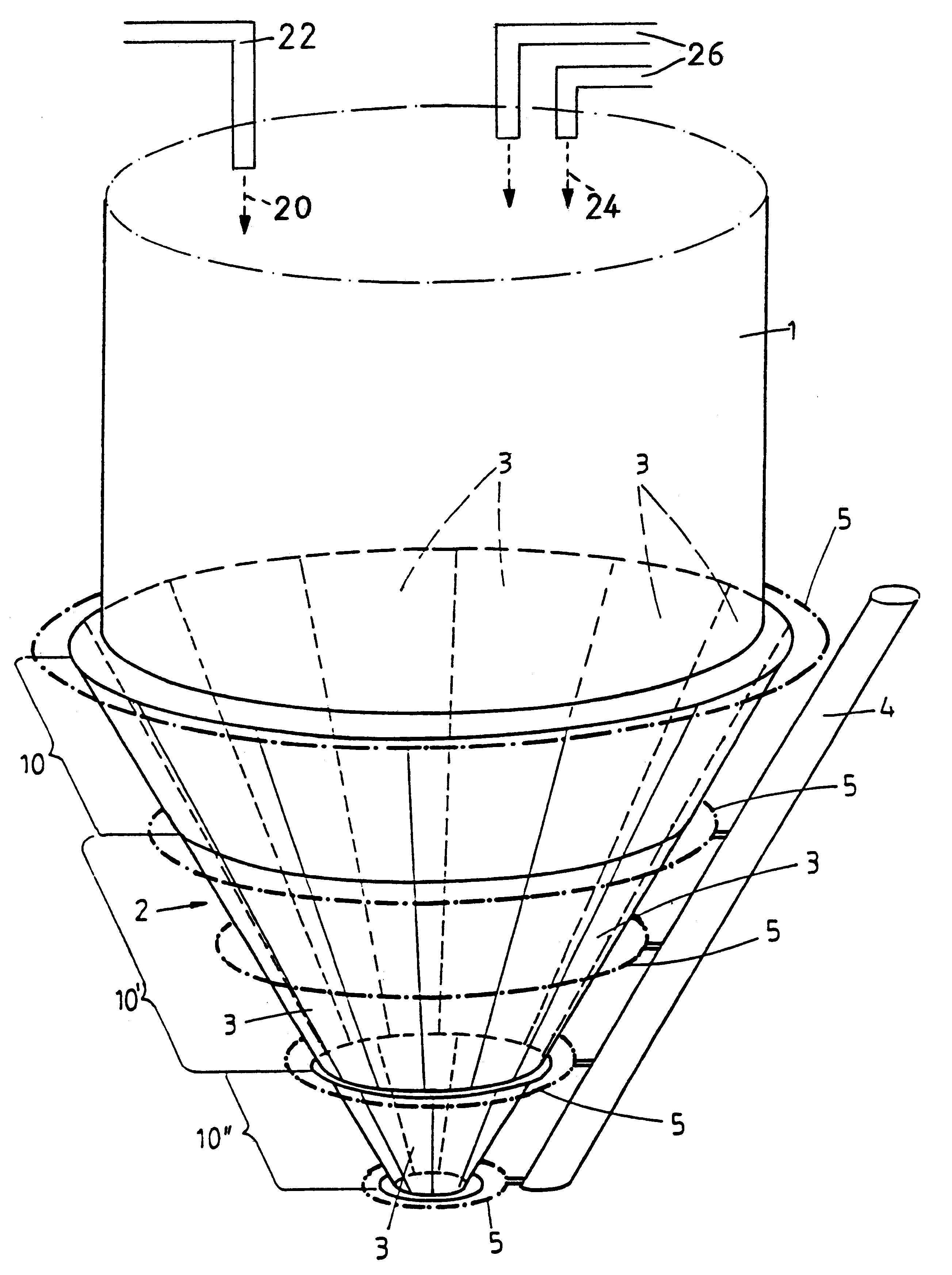
According to the invention, the solution to this problem in a spray dryer of the type mentioned at the beginning is characterized in that at least part of the inner wall of the drying chamber is lined with an air-permeable textile at a distance from the chamber wall and at least one outlet for compressed gas, more particularly compressed air, is provided between the chamber wall and the textile. In a preferred embodiment, the lower part of the inner wall and / or the inner wall in the vicinity of the spraying elements and / or the inner wall below this region is / are lined with the textile.

The particles adhering to the inner walls of the spray dryer according to the invention are deposited onto the air-permeable textile which can be cleaned simply and effectively from the back by exposure to a pulse of the compressed gas. When cleaned in this way, the textile expands and adhering particles fly off and are blown into the interior of the drying chamber. There is no longer any need to inter...


PUM


Abstract

A spray dryer apparatus and method suitable for the production of detergents, cleaners and components thereof wherein the inner wall of the drying chamber is provided with an air-permeable textile material lining at a distance from the inner wall, and at least one outlet for compressed gas is provided between the inner wall and the textile material lining whereby adherence of sticky deposits on the inner wall of the drying chamber is avoided or reduced.

Description

1. Field of the InventionThis invention relates to a spray dryer which is particularly suitable for the production of detergents and / or cleaners and components thereof and which comprises a drying chamber, at least one spraying element for introducing the material to be spray-dried into the chamber and means for introducing a heated gas into the chamber in co-current or countercurrent to the descending spray-dried material.2. Discussion of Related ArtSpray dryers of the type in question are known. They are used on an industrial scale for the production of powder-form detergents or cleaners and components thereof known as "tower powders". In these spray dryers, a coherent liquid mass or slurry is divided up by nozzles into small droplets which are then dried by a hot air stream flowing in countercurrent to the descending droplets, the liquid suddenly evaporating.Spray drying in the production of detergents / cleaners is characterized on the one hand by the relatively high temperature o...

Claims


Application Information

Patent Timeline
IPC IPC(8): B01D1/16B01D1/18F26B3/12F26B3/02C11D11/02
CPCB01D1/18F26B3/12C11D11/02
Inventor VAN DEN MEERSCHE, JAN
Owner HENKEL KGAA
Learn More