
Very high data rate soliton regenerator

a soliton regeneration and data rate technology, applied in the field of very high data rate soliton regeneration, can solve the problems of limiting the maximum frequency to about 40 gbit/s, increasing the cost of devices, and putting a theoretical limit on the quality or the rate at which soliton transmission can take pla

Inactive Publication Date: 2001-05-29
ALCATEL LUCENT SAS
View PDF8 Cites 20 Cited by
  • Summary
  • Abstract
  • Description
  • Claims
  • Application Information

AI Technical Summary

Benefits of technology

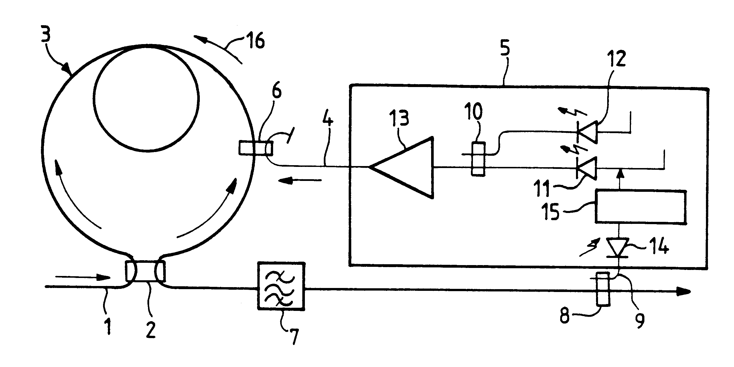
The present invention proposes an original and simple solution to the problem of regenerating solitons by synchronous modulation. It makes it possible to use electronic components of low frequency only even with transmissions having a potential of several hundreds of Gbit / s. In addition, the components of the invention are suitable for being submerged and can therefore be used without difficulty in transoceanic transmission systems.
It is possible to provide means for servo-controlling the variable frequency of at least one of the two sources as a function of the mean power of the modulated soliton signal.
It is also possible to provide means for servo-controlling the variable frequency of at least one of the two sources as a function of the difference between the mean powers of the modulated soliton signals as transmitted and as reflected by the non-linear optical loop mirror.
Finally, it is possible to servo-control the variable frequency of at least one of the two sources by an optical phase-lock loop for locking the beat signal from the two light sources on the soliton signal.
It is possible for a signal of low frequency compared with the data frequency of the soliton signal to be injected into the control signal, and for synchronous detection to be performed.

Problems solved by technology

This effect, which is known as the "Gordon-Haus" effect, puts a theoretical limit on the quality or on the rate at which soliton transmission can take place.
Conventional electro-optical means, such as a directly modulated laser diode, or using external modulation by means of a MachZehnder interferometer, require high frequency electronic components to be used, thereby increasing the cost of devices, and limiting the maximum frequency to about 40 Gbit / s.

Method used


Image

  • Very high data rate soliton regenerator
  • Very high data rate soliton regenerator
  • Very high data rate soliton regenerator

Examples


second embodiment

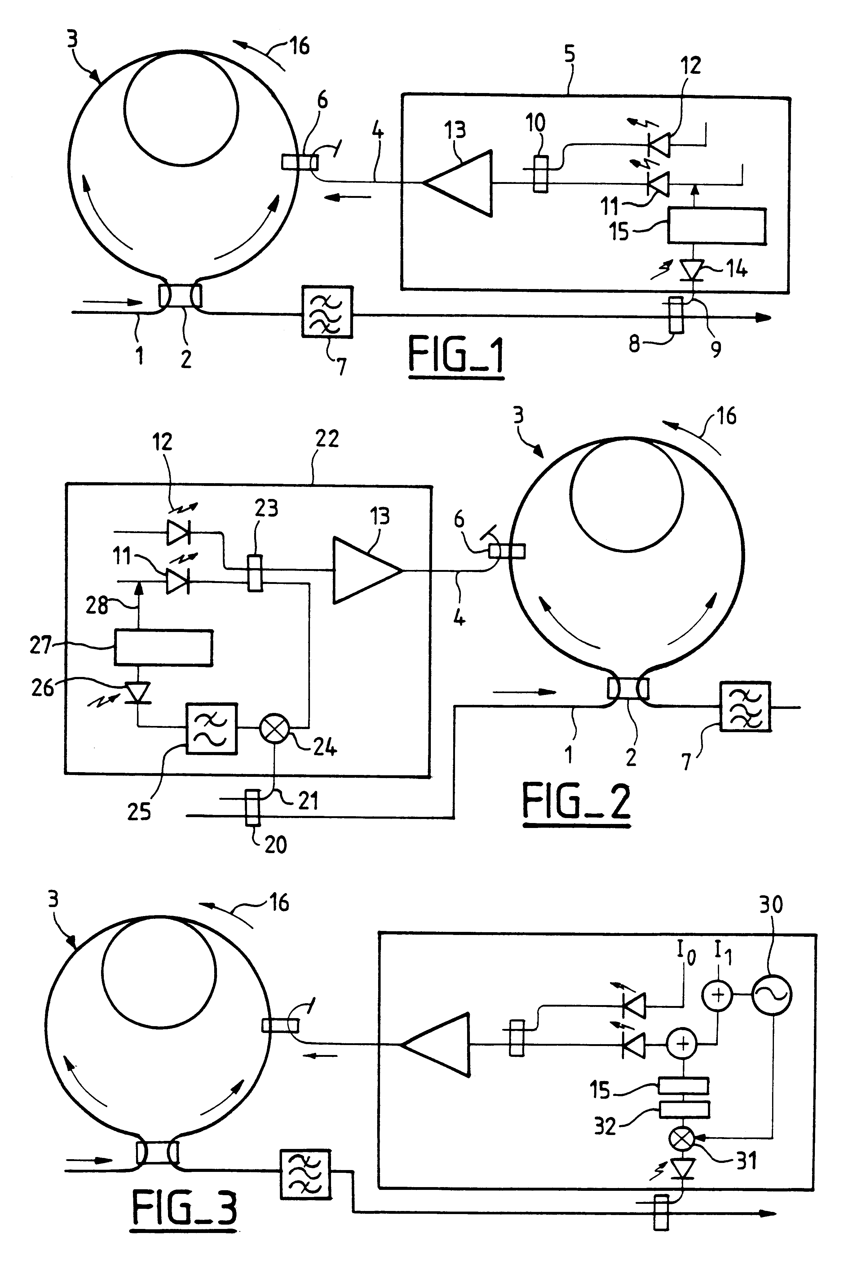
FIG. 2 is a block diagram of the invention in which the frequency of one of the laser sources is servo-controlled by means of an optical phase-lock loop (OPLL). Instead of the elements 8, 9, and 5 of FIG. 1, the device of FIG. 2 has the following elements. Downstream from the NOLM, a coupler 20 couples the fiber 1 to a length of fiber 21. The signal from the fiber 21, taken from the soliton signal that is to be modulated, is applied to a signal regenerator device 22. Like the device 5 in FIG. 5, this device comprises two laser sources 11 and 12 similar to the sources in FIG. 1. The second source 11 is servo-controlled, e.g. by means of its power supply current. Its outlet optical signal has a frequency that differs by f.sub.0 / 2 relative to the signal from the source 12. The outlet signals from the sources 11 and 12 are delivered to a two-inlet optical combiner 23. As in FIG. 1, one of the outlets from the combiner 23 is applied to an amplifier 13. The outlet from the amplifier 13 i...

third embodiment

FIG. 3 is a block diagram of a regenerator of the invention. Compared with the circuit of FIG. 1, the FIG. 3 circuit has the following differences. A source 30 at a frequency f that is small compared with the bit frequency f.sub.0 is added into the current I.sub.1. Also, between the low frequency detector 14 and the control electronics 15, there is inserted a mixer 31 and a lowpass filter 32. The mixer also receives a signal from the source 30.

The FIG. 3 regenerator operates in a manner substantially analogous to the FIG. 1 regenerator. However, the optical signal emitted by the laser source 11 also has a component at the frequency f. Providing the frequency f is very small compared with the bit frequency f.sub.0 of the solitons, that is not troublesome. The mixer 31 mixes the low frequency signal delivered by the detector 14 with the signal at frequency f. The filter 32 eliminates noise from the signal supplied by the mixer, thereby improving the quality of the error signal applied...

fourth embodiment

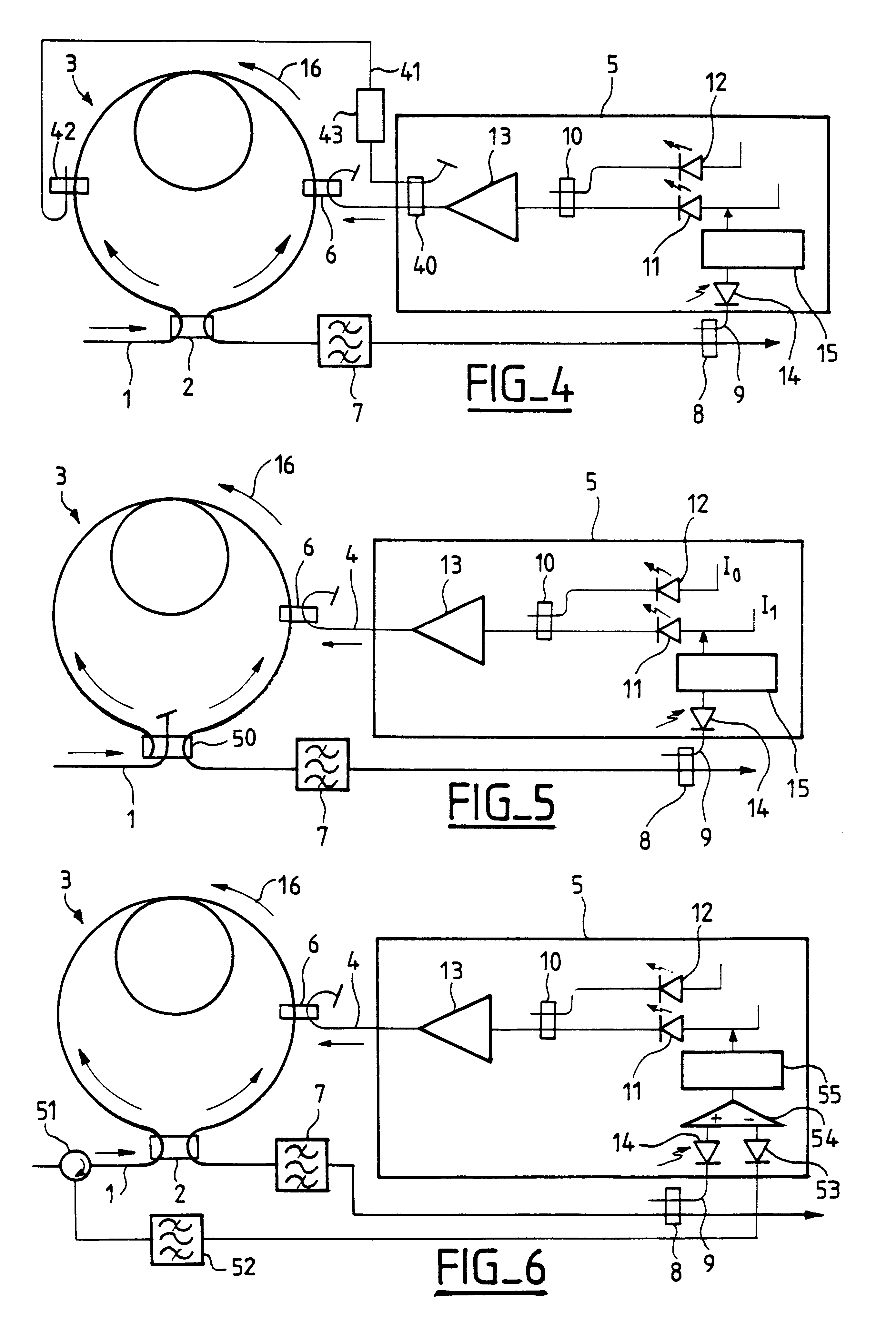
FIG. 4 is a block diagram of a regenerator of the invention. Compared with the FIG. 1 regenerator, the regenerator of FIG. 4 has the following differences: downstream from the amplifier 13 there is disposed a coupler 40 having a 50 / 50 coupling ratio, coupling a control signal into a fiber 41, which control signal is constituted by half of the outlet signal from the amplifier. The control signal coupled into the fiber 41 is coupled into the NOLM by means of a coupler 42 which is symmetrical to the coupler 6, and it propagates in the opposite direction to the control signal which is coupled into the NOLM via the coupler 6. In addition, means are provided for ensuring that the two control signals coupled into the NOLM by the couplers 6 and 42 are in phase opposition: for this purpose, it is possible to provide an appropriate difference in fiber length between the couplers 40 and 6 and between the couplers 40 and 42. It is also possible to provide an optical delay line 43 in the fiber b...


PUM

PropertyMeasurementUnit
lengthaaaaaaaaaa
widthaaaaaaaaaa
latency timeaaaaaaaaaa

Abstract

The invention provides a regenerator for very high rate solitons, the regenerator comprising a non-linear loop mirror or NOLM receiving the soliton signal and modulating it with a control signal. The regenerator also comprises a device for generating the control signal by beats between two light sources, with the frequency of at least one of the two sources being variable and servo-controlled as a function of the modulated soliton signal, e.g. as a function of its power, or servo-controlled by means of an optical phase-lock loop. This provides a soliton regenerator in which the electronic components operate at low frequency only, while being capable of regenerating a soliton signal at a very high rate.

Description

The present invention relates to a very high data rate soliton regenerator, and to a method of regenerating solitons at a very high data rate.The transmission of soliton pulses or solitons of hyperbolic secant envelope, in the portion of an optical fiber having abnormal dispersion is a known phenomenon. The transmission of so-called "black" solitons, constituted by pulse gaps in a continuous signal, in the portion of an optical fiber having normal dispersion is also known; in this case the solitons are of a wavelength such that they propagate with negative chromatic dispersion. Both with "white" solitons and with "black" solitons, the non-linearity in the corresponding portion of the fiber used to compensate dispersion of the optical signal. Soliton transmission is modelled in known manner using the non-linear Schrodinger equation.Various effects limit the transmission of such pulses, such as the jitter imparted by interaction between solitons and the noise present in the transmissi...

Claims


Application Information

Patent Timeline
Patent Type & Authority Patents(United States)
IPC IPC(8): G02F1/35H04B10/18H04B10/07H04B10/25H04B10/516H04B10/61
CPCG02F1/3519H04B10/25077
Inventor BIGO, SEBASTIENVENDROME, GILLES
Owner ALCATEL LUCENT SAS
Learn More