Tool and cutting head for cutting machining

Inactive Publication Date: 2001-06-05
SECO TOOLS AB
View PDF11 Cites 35 Cited by
  • Summary
  • Abstract
  • Description
  • Claims
  • Application Information

AI Technical Summary

Benefits of technology

One object of the present invention is to provide a coupling for two to

Problems solved by technology

Such tools, when being of small dimensions have been found to lack sufficient s

Method used


Image

  • Tool and cutting head for cutting machining
  • Tool and cutting head for cutting machining
  • Tool and cutting head for cutting machining

Examples


Embodiment Construction

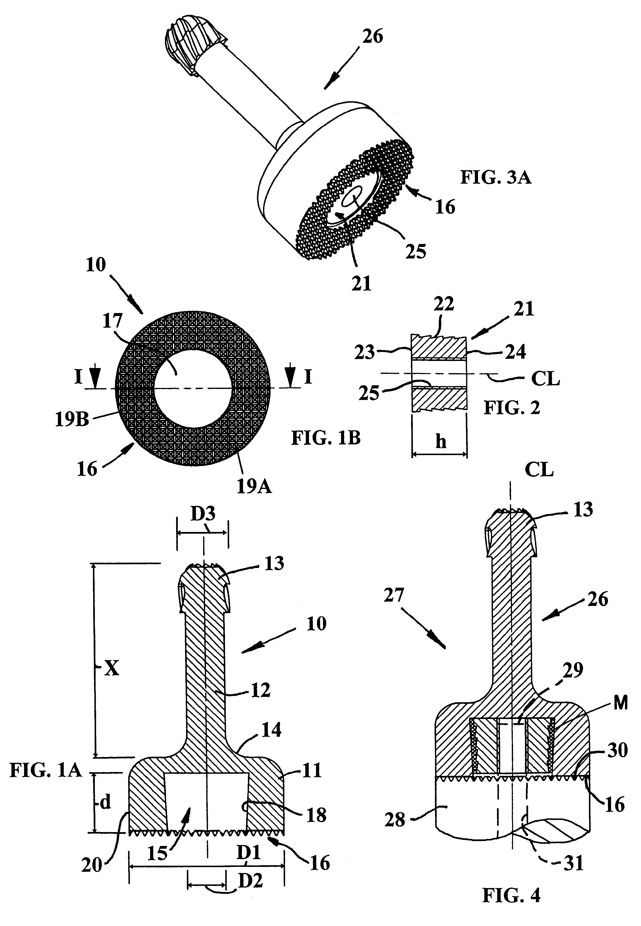
FIGS. 1A and 1B show a, preferably injection molded, hard metal (e.g., cemented carbide) carrier portion 10 according to the present invention. The hard metal carrier portion 10 has a cylindrical basic shape and comprises a base or support portion 11, which connects to an intermediate shank portion 12, which in turn connects to a cutting edge portion 13 provided at the free end of the carrier portion 10. The base 11 has a diameter D1, which is substantial greater than the diameter D2 of the intermediate part 12 and the diameter D3 of the cutting edge portion 13. The diameter D3 is somewhat greater than the diameter D2 to create space for chips during drilling or milling. The portion 13 has, in this example, the shape of a rotary file with a number of bent cutting edges but may alternatively have a drill geometry with only two edges extending towards the rotational axis CL. In case the portion 13 is a drill, it is an advantage if also the part 12 has chip flutes for conducting-away c...


PUM

PropertyMeasurementUnit
Forceaaaaaaaaaa
Diameteraaaaaaaaaa
Lengthaaaaaaaaaa

Abstract

A tool for cutting machining includes a holder, a cutting head and a threaded fastener for fastening the cutting head to the holder. The cutting head is formed of injection molded cemented carbide and includes at least one cutting edge. The holder has a front surface and the cutting head has a support surface provided to releasably abut the front surface substantially in a radial plane. A central blind hole is provided in the support surface. An insert formed of a material softer than injection molded cemented carbide is secured in the blind hole. The insert includes a thread cooperating with a thread of the fastener for pulling the cutting head toward the holder in response to rotation of the fastener. By further tightening the fastener after the support surface abuts the front surface of the holder, the contact between the thread of the fastener and the thread of the insert forces the insert radially outwardly against a wall of the blind bore.

Description

The present invention relates to a machining tool and a cutting head therefor.PRIOR ARTThrough U.S. Pat. No. 5,947,660 there is previously known a tool in which a cutting head is mounted on a rotatable holder. The cutting head has a blind hole formed in a rear surface thereof facing a front surface of the holder. A fastener screw extends axially through the holder and is threadedly connected within the blind hole to pull the rear surface and the front surface against one another. The rear surface of the cutting head and the front surface of the holder include ribs and grooves that form an interlocking relationship in response to rotation of the fastening screw. Such tools, when being of small dimensions have been found to lack sufficient strength or stability in the coupling between the cutting head and the tool body.OBJECTS OF THE INVENTIONOne object of the present invention is to provide a coupling for two tool parts, whereby a great load capacity can be transferred therebetween.A...

Claims


Application Information

Patent Timeline
IPC IPC(8): B23B31/10B23B31/11B23C5/10
CPCB23B31/11B23B2260/132Y10T408/90993Y10T279/16Y10T408/9098Y10T409/30952B23B51/00
Inventor RYDBERG, CHRISTERKOSKINEN, JORMA
Owner SECO TOOLS AB
Why Eureka
Try Eureka