
Magnetic recording medium and method for producing the same

a recording medium and magnetic technology, applied in the field of magnetic recording mediums, can solve the problems of reducing the noise of the medium, reducing the size of the crystal grains, and difficult to make the crystal grains smaller

Inactive Publication Date: 2001-06-05
PANASONIC CORP
View PDF10 Cites 30 Cited by
  • Summary
  • Abstract
  • Description
  • Claims
  • Application Information

AI Technical Summary

Benefits of technology

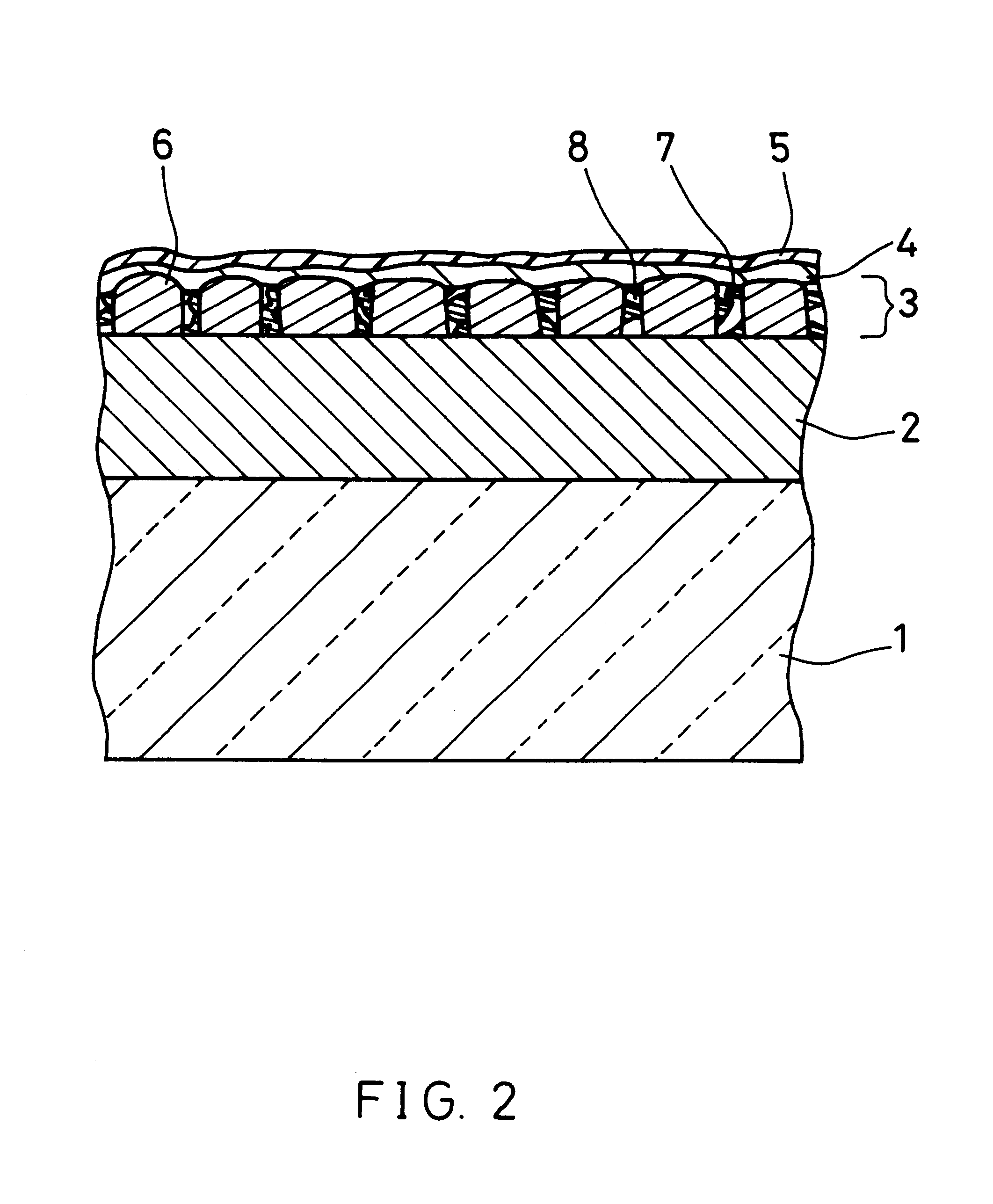
When a magnetic substance and a non-magnetic substance that do not form a solid solution are sputtered simultaneously in an atmosphere having a relatively high pressure, clusters in which fine magnetic grains are aggregated are formed, and the isolation of the clusters from each other is facilitated.
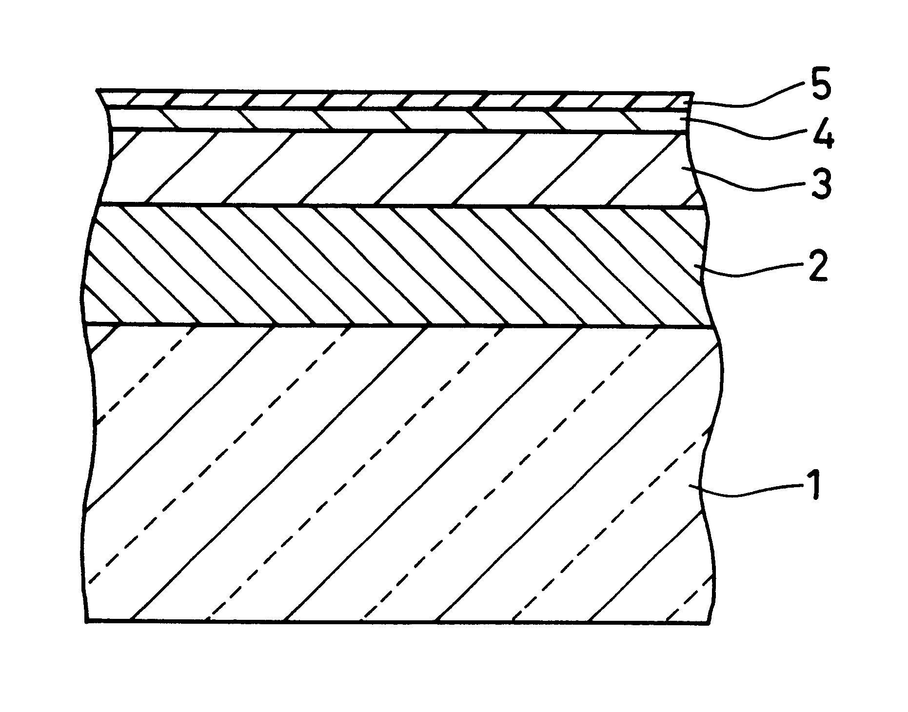
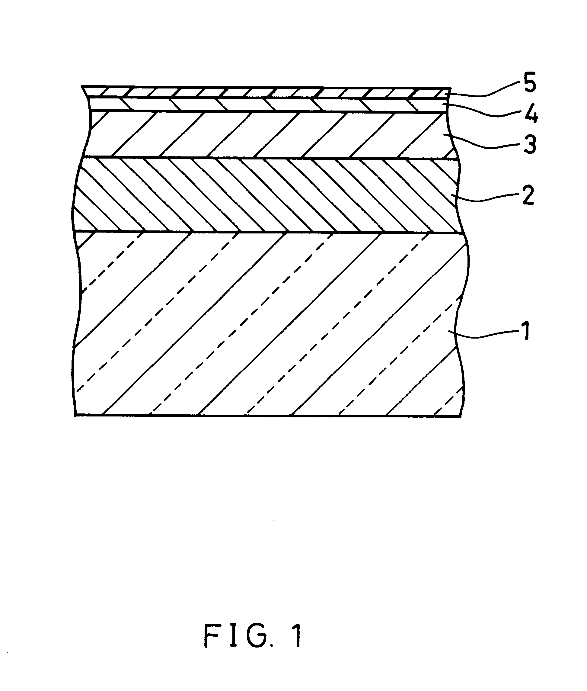
According to the present invention, a magnetic layer formed on a non-magnetic substrate and an underlying layer comprises clusters of aggregated magnetic grains having a grain diameter of 5 nm to 20 nm and a non-magnetic substance between the clusters. Furthermore, an average gap between the clusters is 1.5 nm to 5 nm. Therefore, the present invention can provide a magnetic recording medium having low noise and a high S / N ratio, which is suitable for high density recording. This magnetic recording medium can be formed efficiently by simultaneously sputtering a magnetic substance and a non-magnetic substance that does not form a solid solution with the magnetic substance in an atmosphere having a pressure of 30 mTorr to 75 mTorr, in the step of forming the magnetic layer on an underlying layer formed on a non-magnetic substrate.

Problems solved by technology

Thus, it is difficult to make the crystal grains smaller.
A large size of crystal grains is detrimental to a decrease in medium noise.
It is likely that a smaller gas pressure results in smaller voids between clusters.
On the other hand, when the gas pressure is excessively large, the obtained magnetic layer has sparse clusters, so that the contact with the head at the time of CSS may damage the magnetic medium.
This constitutes a detriment to achieving low medium noise.

Method used


Image

  • Magnetic recording medium and method for producing the same
  • Magnetic recording medium and method for producing the same
  • Magnetic recording medium and method for producing the same

Examples


Embodiment Construction

Hereinafter, the present invention will be more specifically described by way of an example, but the present invention is not limited thereto.

A disk-shaped glass substrate having a diameter of 2.5 inch was placed in an in-line sputtering apparatus. The apparatus was evacuated to reach a vacuum of 10.sub.6.sup.- Torr order. Then, baking was performed at 350.degree. C. for 30 minutes in order to remove gas molecules or the like adhering to the surface of the substrate. After baking, the substrate temperature was lowered by cooling to room temperature (about 25.degree. C., which applies to the following). The degree of vacuum after cooling was 5.times.10.sub.7.sup.- Torr.

A Cr layer was formed as an underlying layer on the glass substrate to a thickness of 100 nm in the in-line sputtering apparatus. Then, a magnetic layer was formed on the Cr layer at a predetermined substrate temperature and a predetermined gas pressure so as to have a thickness of about 15 nm. As the sputtering target...


PUM

PropertyMeasurementUnit
grain diameteraaaaaaaaaa
surface roughnessaaaaaaaaaa
thicknessaaaaaaaaaa

Abstract

An underlying layer is formed of Cr or the like on a glass substrate, and a magnetic layer is formed on the underlying layer by simultaneously sputtering a magnetic substance and a non-magnetic substance that does not form a solid solution with the magnetic substance in an atmosphere having a pressure of 30 mTorr to 75 mTorr. The magnetic recording medium comprises clusters, each of which is formed of aggregated magnetic grains, and a non-magnetic substance between the clusters. Each magnetic grain has a grain diameter of 5 nm to 20 nm. An average gap between the clusters is 1.5 nm to 5 nm. Thus, the present invention can provide a magnetic recording medium having a high S / N ratio that is suitable for high density recording.

Description

1. Field of the InventionThe present invention relates to a magnetic recording medium for use in a magnetic recording / reproducing device having large capacity and high recording density, and a method for producing such a magnetic recording medium.2. Description of the Prior ArtThere is a tendency in a magnetic recording / reproducing device toward high density recording in order to achieve large capacity with a compact size. In the field of a hard disk drive, which is a typical magnetic recording device, a device having a recording density per unit of area (surface recording density) more than 1 Gbit / in.sup.2 has been already commercially available. It is expected to see a technological advancement so rapid that a device with 10 Gbit / in.sup.2 will be commercially practical in a few years.An improvement in medium performance and head-disk interface performance, and an enhancement in a linear recording density resulting from the advent of new signal processing techniques such as partial...

Claims


Application Information

Patent Timeline
Patent Type & Authority Patents(United States)
IPC IPC(8): G11B5/84G11B5/855G11B5/64G11B5/851
CPCG11B5/656G11B5/851G11B5/855Y10T428/26Y10S428/90Y10T428/265G11B5/658
Inventor RYONAI, HIROSHIISHIDA, TATSUAKITOHMA, KIYOKAZUMIYATA, KEIZOUHAMADA, TAIZOU
Owner PANASONIC CORP
Learn More