Superconducting circuit having superconductive circuit device of voltage-type logic and superconductive circuit device of fluxoid-type logic device selectively used therein

Inactive Publication Date: 2001-06-05
NEC CORP +1
View PDF8 Cites 84 Cited by
  • Summary
  • Abstract
  • Description
  • Claims
  • Application Information

AI Technical Summary

Problems solved by technology

An example of the superconducting memory of the fluxoid-type logic device has one dimensional arrangement, because a two-dimensional array is hardly achieved.
However, any superconducting random access memory of the fluxoid-type logic device has not been developed, yet.
First, the prior art superconducting random access memory of the voltage-type logic device is implemented by the latching devices, and the latching devices requires a large amount of high-frequency alternating current bias.
Thus, the problem inherent in the prior art superconducting random access memory of the voltage-type logic device is a large amount of electric power consumption.
Although the prior art superconducting random access memory of the fluxoid type logic device is superior in the high-speed operation and the electric power consumption than the prior art superconducting random access memory of the voltage-type logic device, it is difficult to arrange the memory cells in matrix.
Thus, the problem inherent in the prior art superconducting random access memory is the layout of memory cells.
The prior art superconducting NOR circuit of the voltage-type logic device also has a problem in the large amount of power consumption as similar to the pr

Method used


Image

  • Superconducting circuit having superconductive circuit device of voltage-type logic and superconductive circuit device of fluxoid-type logic device selectively used therein
  • Superconducting circuit having superconductive circuit device of voltage-type logic and superconductive circuit device of fluxoid-type logic device selectively used therein
  • Superconducting circuit having superconductive circuit device of voltage-type logic and superconductive circuit device of fluxoid-type logic device selectively used therein

Examples


second embodiment

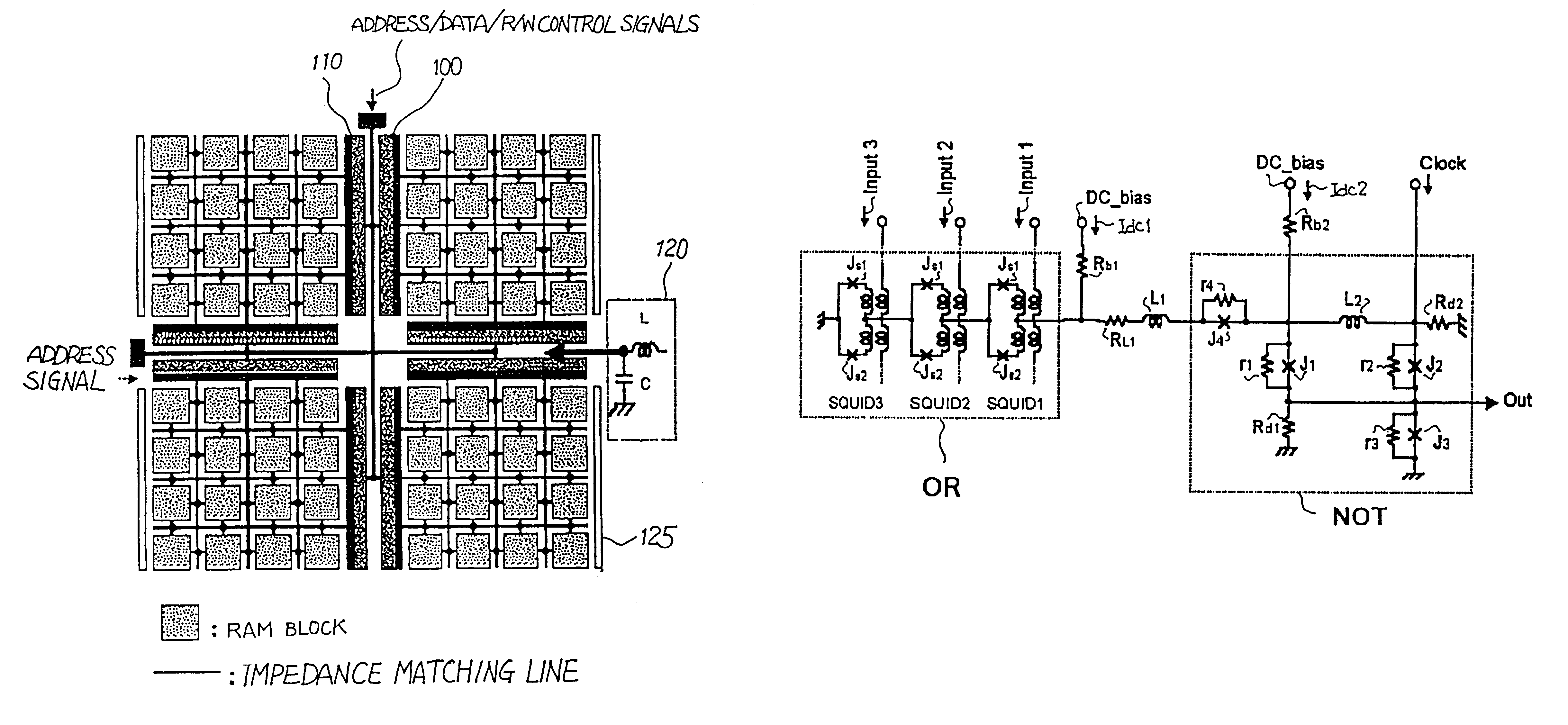
FIG. 7 illustrates a superconducting NOR gate embodying the present invention. The superconducting NOR circuit comprises a magnetically coupled multi-input superconducting OR circuit OR, a superconducting NOT circuit NOT, bias feed resistors Rb1 / Rb2, a load resistor RL1 and an inductor L1. The superconducting OR gate OR is connected through the bias feed resistor Rb1 to a source of direct bias current, and the superconducting NOT circuit NOT is connected through the bias feed resistor Rb2 to the source of direct bias current. The source of direct bias current supplies direct bias current Idc1 to the superconducting OR circuit OR and direct bias current Idc2 to the superconducting NOT circuit NOT.

The superconducting OR circuit OR includes superconducting quantum interference devices SQUID1 / SQUID2 / SQUID3, and the superconducting quantum interference devices SQUID1 / SQUID2 / SQUID3 are coupled in series between the load resistor RL1 and the ground. The superconducting quantum interference...

third embodiment

FIG. 9 illustrates a superconducting decoder circuit embodying the present invention. The superconducting decoder circuit comprises eight superconducting NOR circuits 200 / 210 / 220 / 230 / 240 / 250 / 260 / 270, superconducting driver circuits 280 and terminating resistors 290, and, accordingly, eight superconducting OR circuits SFQ_OR and eight superconducting NOT circuits SFQ_NOT form the superconducting NOR circuits 200 to 270 as similar to the superconducting NOR circuit shown in FIG. 7.

All the superconducting NOR circuits 200 to 270 are biased with direct current, and all the superconducting driver circuits 280 are biased with alternating current. Thus, the superconducting NOR circuits 200 to 270 are constituted by the SFQ devices, and the superconducting driver circuits 280 are constituted by the latching devices. A three-bit address signal A / B / C and inverted address bits CA / CB / CC are supplied to the driver circuits 280, and the driver circuits 280 are selectively connected to the superco...

fourth embodiment

FIG. 10 illustrates a superconducting signal converting circuit embodying the present invention. The superconducting signal converting circuit comprises Josephson junctions J1 / J2 / J3, damping resistors Rd1 / Rd2, an inductor L1 and bias feed resistors Rb1 / Rb2. The series combination of the inductor L1, the Josephson junction J3 and the damping resistor Rd2 is connected between an input node and the ground, and an input signal In is supplied to the input node. The input signal is SFQ pulses. Although the damping resistor Rd2 is grounded at one end thereof, the grounded end serves as an output node, which is connected to an input node of the next stage. An output signal Out is obtained at the output node, and is a level signal.

A source DC of direct bias current is connected to the bias feed resistor Rb1, and direct bias current Idc flows from the source DC through the bias feed resistor Rb1 to the parallel combination of the damping resistor Rd1 and the Josephson junction J1. The paralle...


PUM


Abstract

A superconducting circuit device of a voltage-type logic device is large in current driving capability and, accordingly, electric power consumption; however, the switching speed is not so fast, and a superconducting circuit device of a fluxoid-type logic device is small in current driving capability and, accordingly, the electric power consumption; however the switching speed is faster than that of the superconducting circuit device of the voltage-type logic device, wherein the superconducting circuit device of the voltage-type logic device and the superconducting circuit device of the fluxoid-type logic device are selectively used in a superconducting circuit such as a superconducting random access memory, a superconducting NOR circuit and a superconducting signal converting circuit so as to realize small electric power consumption and high-speed switching action.

Description

This invention relates to a superconducting circuit and, more particularly, to a superconducting circuit using a Josephson junction as a circuit device.DESCRIPTION OF THE RELATED ARTAn integrated circuit using the Josephson junctions is hereinbelow referred to as "superconducting integrated circuit". The superconducting integrated circuits are broken down into two categories. The first category is a voltage-type logic device, and uses the non-linearity of the voltage-to-current characteristics of the Josephson junction. The logic gates categorized in the voltage-type logic device achieves the logic functions already known in the semiconductor logic gates. Another category uses the non-linearlity of the current phase characteristics of the Josephson junction, and is called as "fluxoid type logic device".A superconducting integrated circuit of the voltage-type logic device outputs a constant voltage for a constant period. The output potential level is changed between state "0" and sta...

Claims


Application Information

Patent Timeline
IPC IPC(8): G11C11/21G11C11/44H03K19/02H03K19/195
CPCG11C11/44H03K19/1958
Inventor NAGASAWA, SHUICHIMIYAHARA, KAZUNORIENOMOTO, YOUICHI
Owner NEC CORP
Why Eureka
Try Eureka