
Process and apparatus for sputter etching or sputter coating

Inactive Publication Date: 2001-06-19
OERLIKON ADVANCED TECH
View PDF10 Cites 59 Cited by
  • Summary
  • Abstract
  • Description
  • Claims
  • Application Information

AI Technical Summary

Benefits of technology

confining a discharge space in said recipient defined by said first and second electrode surfaces, thereby preventing an RF discharge generated between said first and second electrode surfaces to spread outside said confinement;
It is a further object of the present invention to additionally achieve, by the inventively applied magnetic field, control of the distribution of sputtering along the surface to be sputtered. This is realized by controlling such distribution by increasing plasma density adjacent the surface to be sputtered and at selected loci by the magnetic field inventively applied.

Problems solved by technology

Thus, according to the said KOENIG law, the "cathode" surfaces will be exclusively sputtered and all the counter-electrode surfaces will not be sputtered, because, there, kinetic ion energy is not sufficient.
Applying the law of KOENIG to this arrangement reveals that due to the large ratio of electrode surface areas confining the RF discharge space, the average kinetic energy of ions will only suffice for considerable sputtering at the workpiece carrier electrode.
Thereby, ion acceleration at the latter is, averaged, insufficient to lead to significant surface sputtering.
Thereby a significant drawback of such technique is that the overall extent of the discharge space and, accordingly of a respective vacuum chamber, is predominantly given by the large extent necessary of the large electrode confining the RF plasma space.
Thus, this large electrode makes the arrangement bulky and does, in fact, not contribute to the extent of surface to be sputtered, which is considerably smaller.
This is due to considerations according to the said law of KOENIG which apparently was believed to be unavoidable.
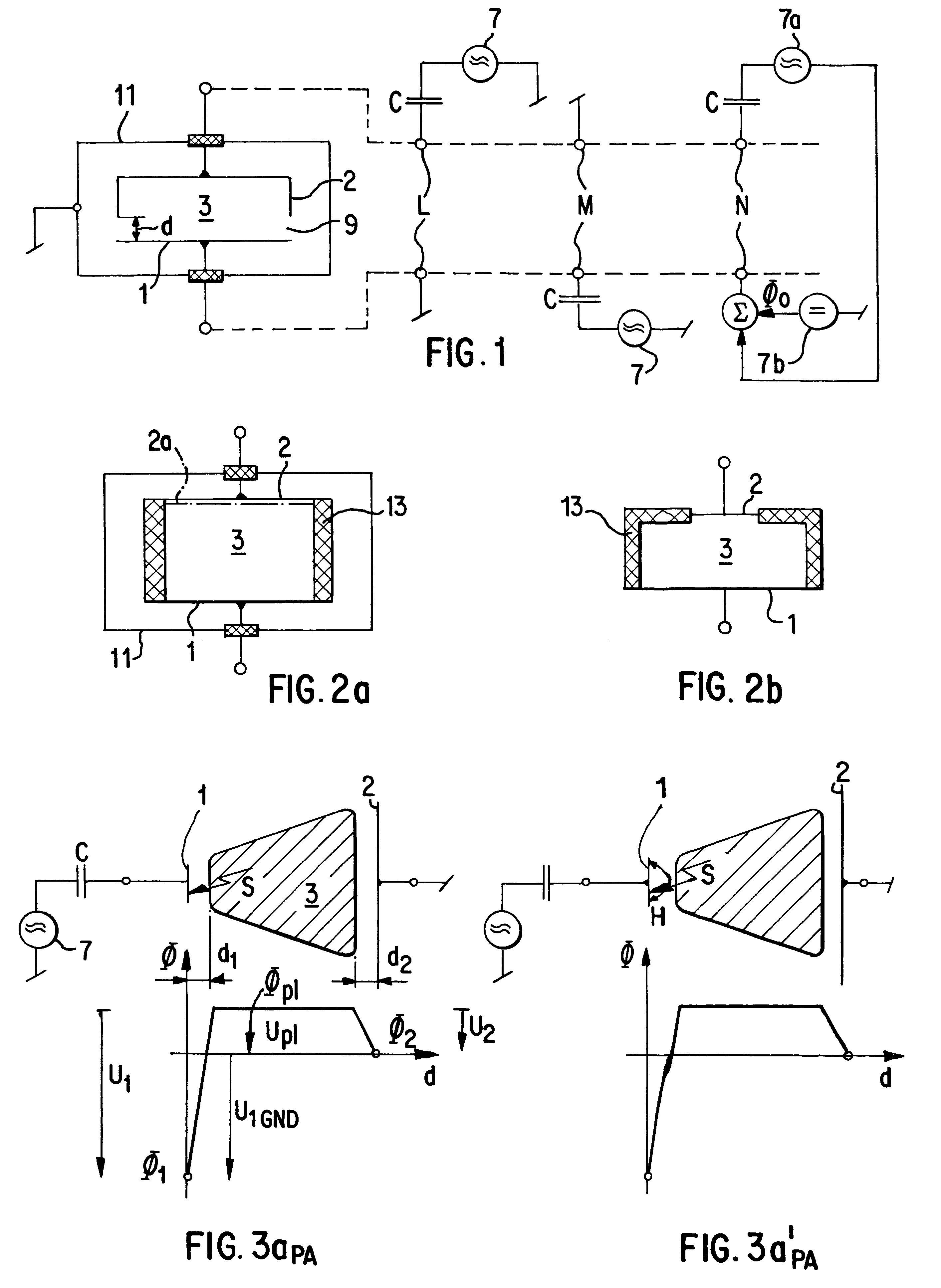
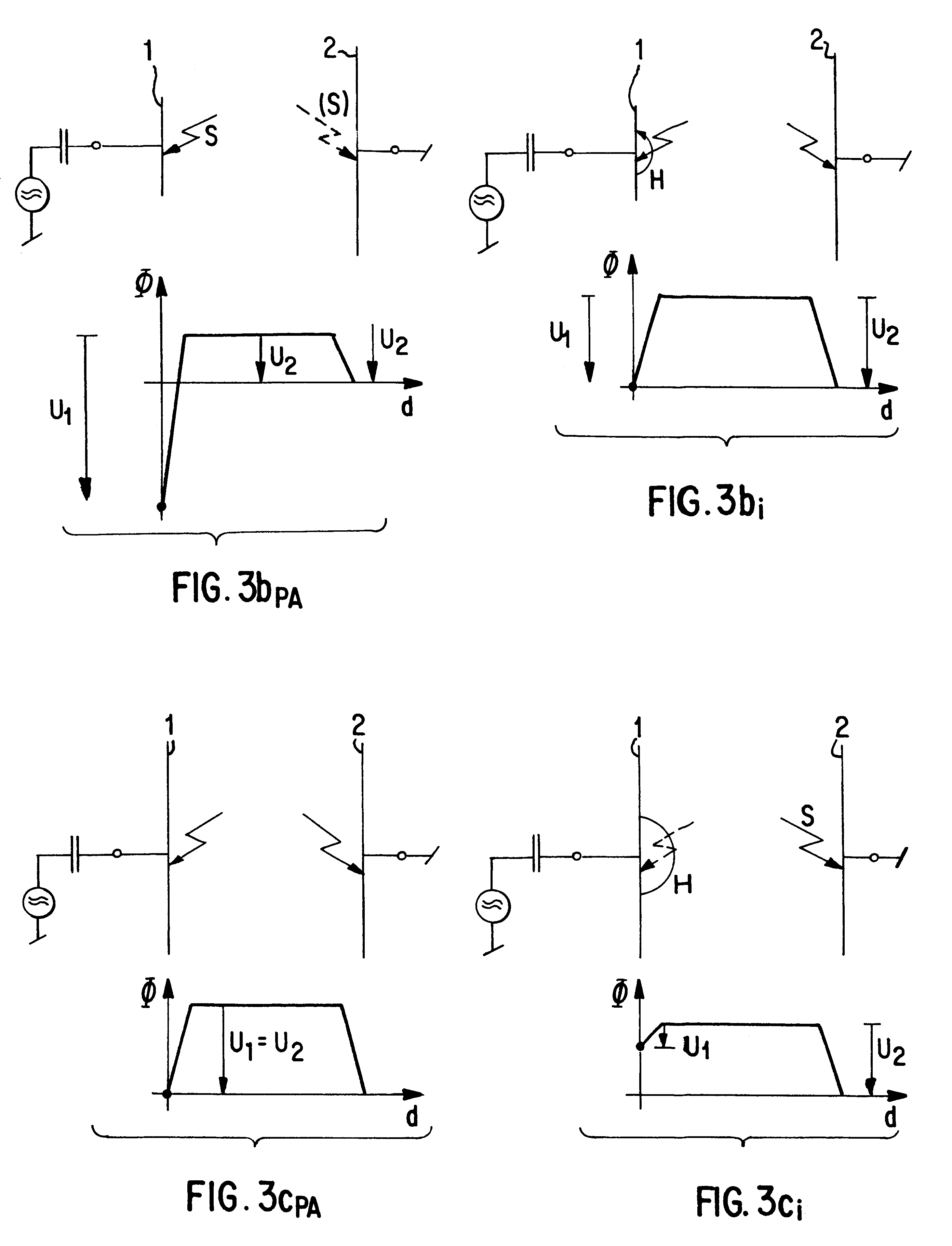
Given these ratios of drops of time-averaged electric potential across the two dark spaces considered, it thus becomes possible to select the absolute values of the said two drops so that the one across the first dark space adjacent to the smaller electrode surface becomes substantially ineffective for sputtering, in that ion acceleration leads there to average kinetic energy which will not suffice to sputter a predetermined material at the smaller electrode.

Method used


Image

  • Process and apparatus for sputter etching or sputter coating
  • Process and apparatus for sputter etching or sputter coating
  • Process and apparatus for sputter etching or sputter coating

Examples


Embodiment Construction

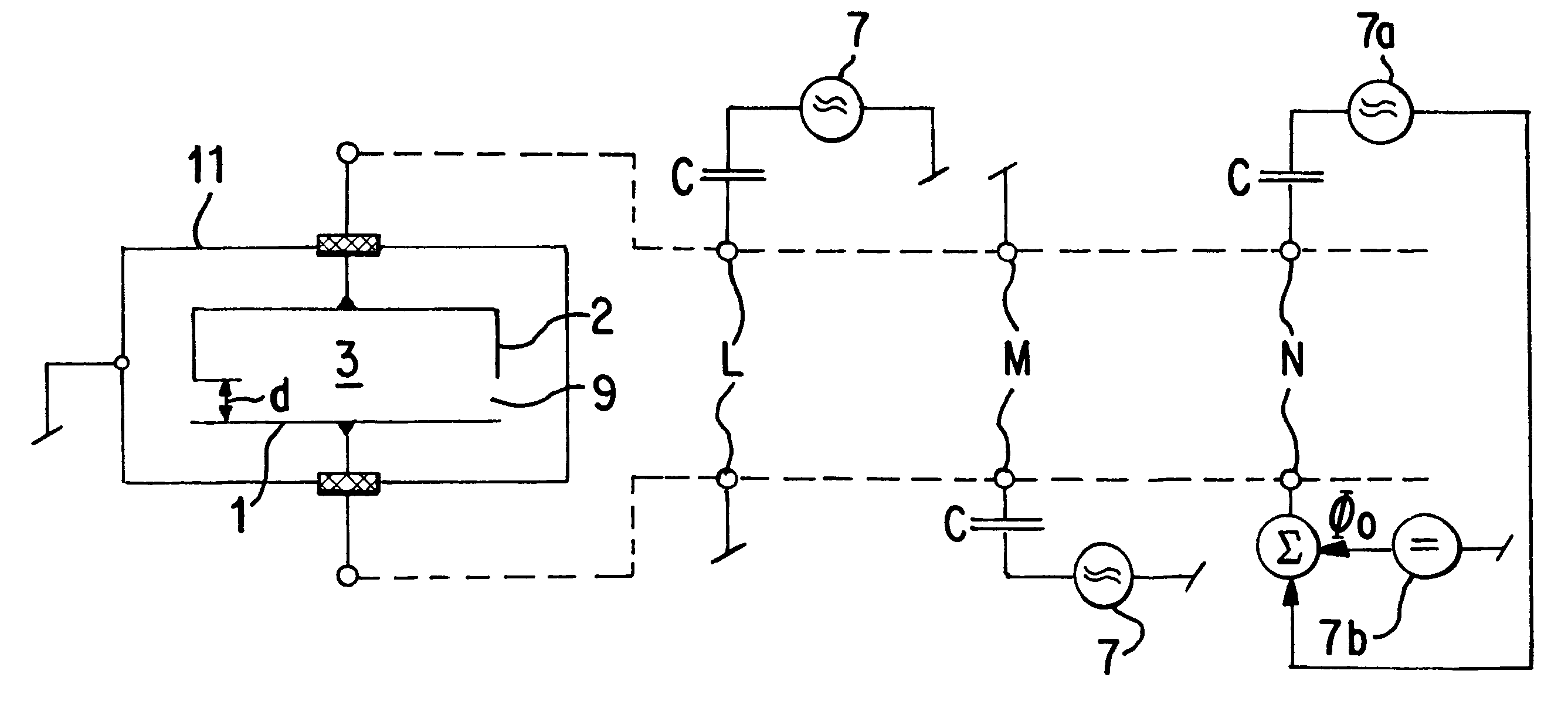
In FIG. 1 an RF plasma discharge space 3 is confined exclusively by two electrodes 1 and 2. As schematically shown by three alternative connections, L, M, N in one case, the electrode 2 is connected to an RF generator 7 via a DC-decoupling capacitor C, whereas electrode 1 is connected to a reference potential, usually to ground potential. As a second variant M, electrode 2, which is shown as being a hollow electrode, is connected to reference potential, normally to ground potential, whereas electrode 1 is connected via a DC-decoupling capacitor C to RF generator 7. As a third and fourth variant (latter not shown), either electrode 1 or 2 is again connected via decoupling capacitor C to an RF generator 7a which itself is not referred to reference potential as RF generator 7, but which is connected to the other electrode 2 or 3. One of the electrodes as shown, e.g. electrode 1, which is not decoupled from DC potential by capacitor C, is set to a reference DC potential .0..sub.o, as e....


PUM

PropertyMeasurementUnit
Lengthaaaaaaaaaa
Lengthaaaaaaaaaa
Lengthaaaaaaaaaa

Abstract

A problem which occurs in the sputtering of a substance by means of a high-frequency discharge between two electrodes, is that both electrode surfaces are sputtered away when the electrode surface that is actually not to be sputtered is not at least ten times as large as the surface of the electrode carrying the substance. To prevent an undesirable cosputtering, in on embodiment, a vacuum recipient at a selected gas pressure has first and a second electrodes which are selected so that their surface areas form a ratio RA 12 such that 0.3<=RA12<=3. A discharge space in the vacuum recipient is confined to the electrode surfaces. An RF plasma discharge is generated in the discharge space by applying an electric RF field between the electrode surface, so that a first dark space region with a first drop of time-averaged electric potential and a second dark space region with a second drop of time-averaged electric potential, are respectively provided adjacent each electrode. The surface of an object to be coated is disposed in the second dark space region adjacent said larger electrode surface so that the surface of the object is at a floating electric potential to perform diode sputtering. A magnetic field is generated within the discharge space, a large part of its lines of force being tunnel-like shaped on the first electrode surface and extending across aid first dark space region to enhance sputtering of the surface of the object.

Description

1. Field of the InventionThe present invention is directed to a process and apparatus for sputtering a surface of a workpiece to be sputter-etched or for sputtering a surface of a target for sputter-coating a workpiece, both referred to as a "sputtering object".More specifically, the present invention is directed to such processes and apparatus, whereat RF sputtering is performed in a vacuum recipient which is filled with a working gas at a selected gas pressure.Even more specifically, the present invention is directed to the application of magnetic fields in such processes and apparatus.2. Description of Prior ArtIn specific art mentioned above, the law of KOENIG as disclosed for instance in H. R. Koenig and L. I. Meissel, IBM Journal Research Development 14, p. 168 (1970), and H. R. Koenig, U.S. Pat. No. 3,661,761 (1969), is well-known. It defines that the ratio of drop of time-averaged electric potential adjacent to electrode surfaces between which an RF plasma discharge is gener...

Claims


Application Information

Patent Timeline
IPC IPC(8): C23C14/35H01J37/32H01J37/34
CPCC23C14/35H01J37/32623H01J37/3266H01J37/3402
Inventor WELLERDIECK, KLAUSWEGMANN, URSHOEFLER, KARL
Owner OERLIKON ADVANCED TECH
Learn More