Programmed electron flux

a technology of electron flux and electron flux, applied in the field of programed electron flux, can solve the problems of not providing the highest level of control and the inability to use prior art control approaches

Inactive Publication Date: 2001-07-03
SIEMENS AG
View PDF5 Cites 71 Cited by
  • Summary
  • Abstract
  • Description
  • Claims
  • Application Information

AI Technical Summary

Problems solved by technology

This approach does not take into account the small variations in electron flux for a fixed filament current and therefore will not provide the highest level of control.
Therefore, the prior art control approaches cannot be used where the FTICR MS is to be used as an unattended monitor of process streams.

Method used


Image

  • Programmed electron flux
  • Programmed electron flux
  • Programmed electron flux

Examples


Embodiment Construction

)

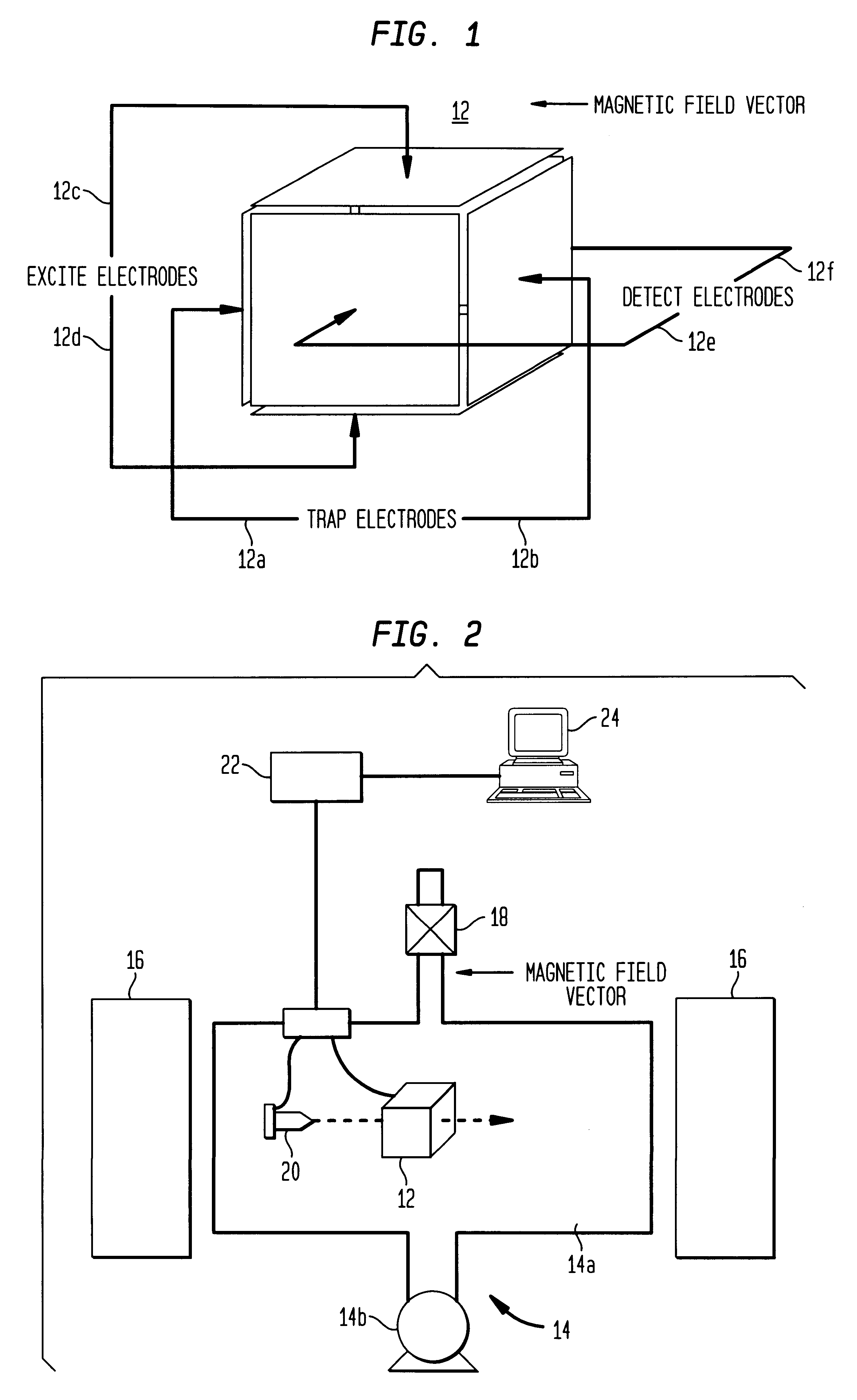
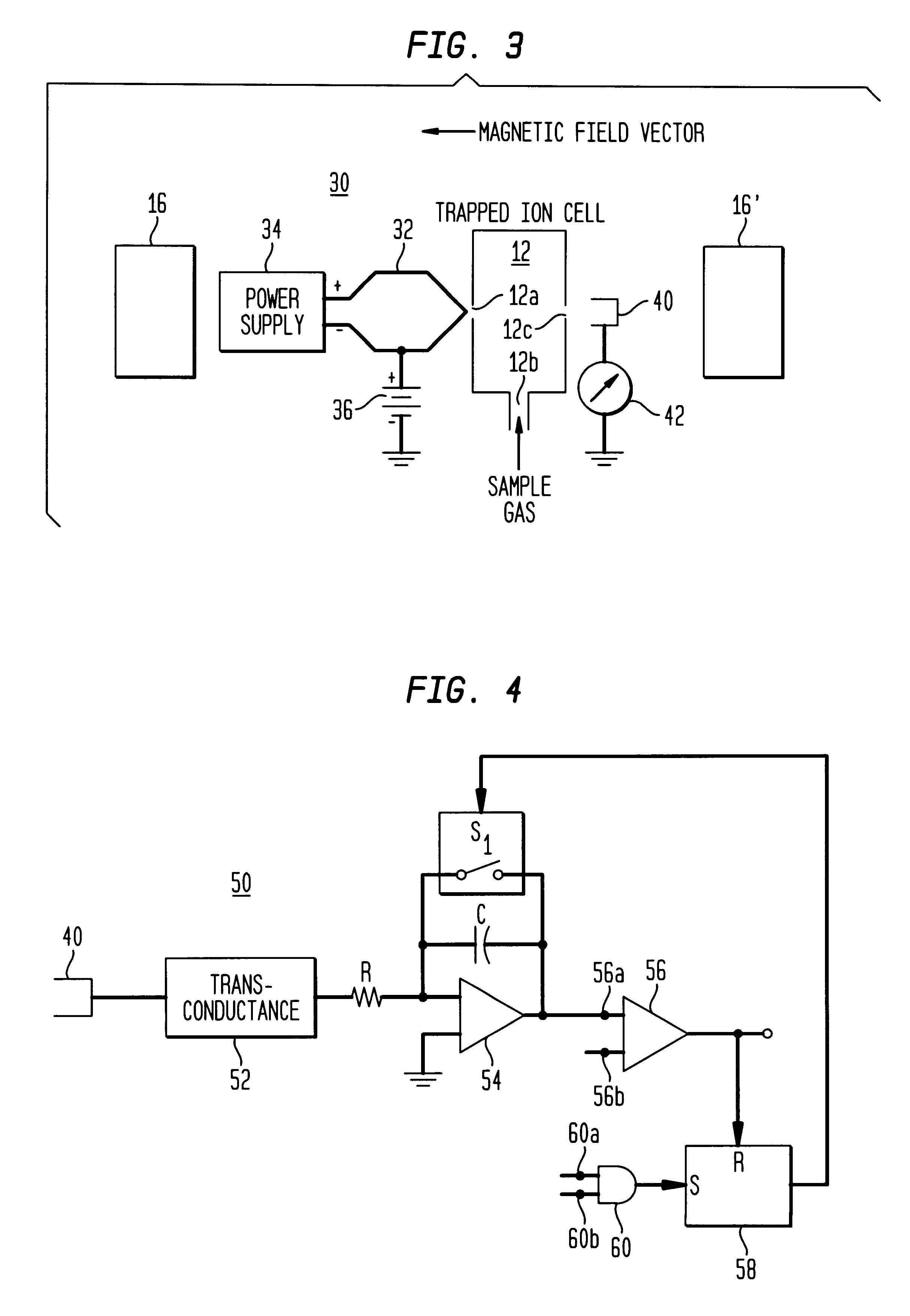
Referring now to FIG. 3, there is shown a simplified diagram of a circuit 30 that is used to produce the electrons which are used in ionize 20 of FIG. 2. Circuit 30 includes an electron source 32, shown in FIG. 3 as a filament, that is connected to a supply 34 that provides the power for heating the filament to incandescence. The electron source 32 is also connected to a source 36 of negative potential. The electron source 32 is placed opposite an opening 12a in trapped ion cell 12 of FIG. 2. The cell has another opening 12b through which the gas sample to be ionized enters the cell and an opening 12c which is opposite opening 12a and adjacent an external collector 40. The collector 40 is connected through an ammeter 42 to ground potential. The accelerated electrons enter cell 12 through opening 12a and exit the cell through opening 12c. Magnet 16 of FTICR MS 10 functions to constrain the electrons and increase the path length as the electrons travel a helical path between electron...


PUM


Abstract

A quantity of electrons that will be used in the ionization event in an FTICR MS is preprogrammed. When the number of electrons produced reaches that number, the electron beam is turned off. This approach assures that the same number of electrons are used for every measurement and eliminates the variations due to fundamental characteristics of the electron sourcere and the variations in temperature due to changing ambient conditions.

Description

This invention relates to a mass spectrometer (MS) which uses the Fourier transform ion cyclotron resonance (FTICR) technique to determine the mass of ions and more particularly to the control of the number of electrons generated during the ionization process to ensure that the same number of electrons are used for each measurement.DESCRIPTION OF THE PRIOR ARTWhen a gas phase ion at low pressure is subjected to a uniform static magnetic field, the resulting behavior of the ion is determined by the magnitude and orientation of the ion velocity with respect to the magnetic field. If the ion is at rest, or if the ion has only a velocity parallel to the applied field, the ion experiences no interaction with the field.If there is a component of the ion velocity that is perpendicular to the applied field, the ion will experience a force that is perpendicular to both the velocity component and the applied field. This force results in a circular ion trajectory that is referred to as ion cyc...

Claims


Application Information

Patent Timeline
Patent Type & Authority Patents(United States)
IPC IPC(8): H01J49/38H01J49/42H01J49/02H01J49/34
CPCH01J49/022H01J49/38H01J49/147
Inventor LITTLEJOHN, DUANE P.ARNOLD, ROBERT W.
Owner SIEMENS AG
Why Eureka
Try Eureka