
Registration control for quality silk screen printing

a registration control and silk screen printing technology, applied in office printing, coatings, printing, etc., can solve the problems of nonconcentric rotation between the rotator, coaxial alignment, and failure to bring the rotational axis of the bottle into

Inactive Publication Date: 2001-07-10
CARL STRUTZ & CO
View PDF10 Cites 16 Cited by
  • Summary
  • Abstract
  • Description
  • Claims
  • Application Information

AI Technical Summary

Benefits of technology

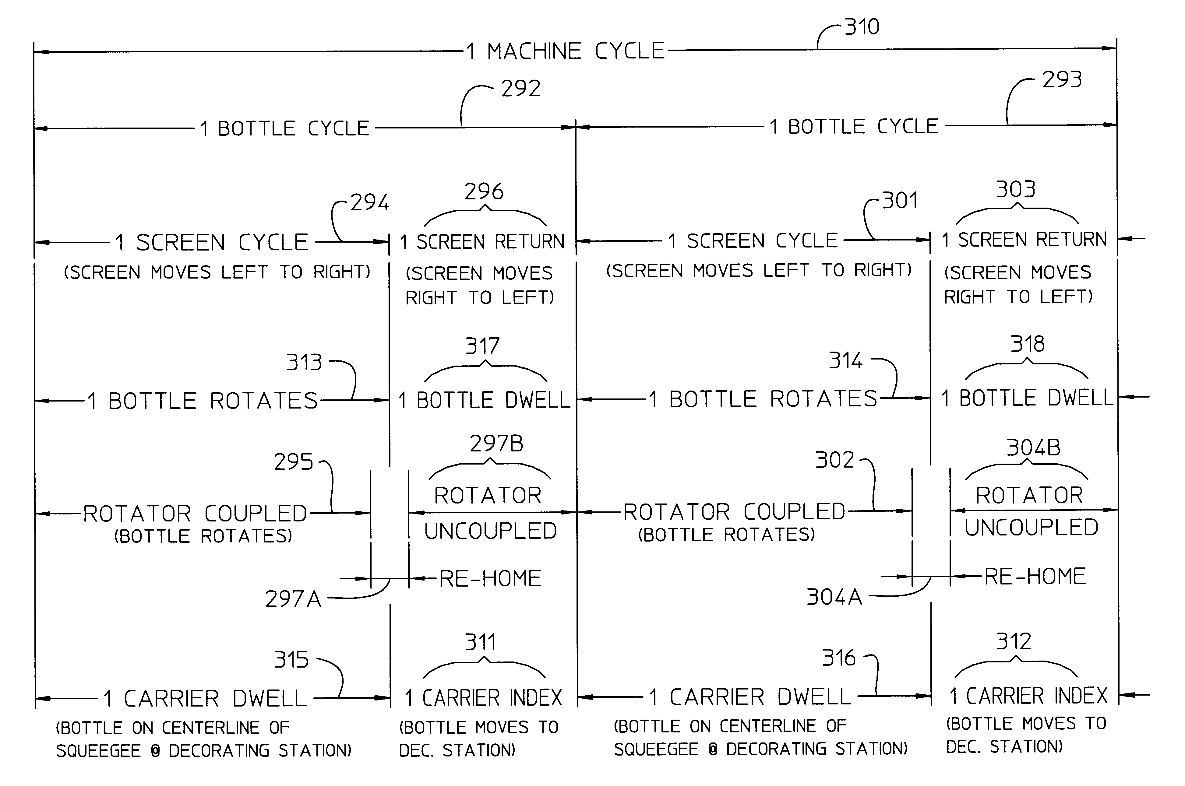
It is an object of the present invention to provide an improved construction and operation for an intermittent motion decorator having a workpiece rotator coupled by a drive controller to a screen drive used to linearly displace a decorating screen synchronously with rotation of a workpiece and after the application of decoration, the drive controller is operable to uncouple the rotator from the screen drive.
It is yet a further object of the present invention to provide an electric control system for correcting position error of a workpiece rotator after decorating a first workpiece to insure a driving relation established with a second workpiece in an intermittent motion decorator to faithfully maintain both workpiece orientation and synchronous speed relation between linear displacement of a decorating screen and surface speed of a rotating workpiece, particularly in intermittent motion decorator machines having a decorator drive cam constructed for unidirectional decorating.
The apparatus of the present invention is useful to provide a method for decorating workpieces advanced to and from a decorating station, the method including the steps of advancing a first workpiece to intermittently reside at a decorating station, establishing a drivenly coupled relation between a workpiece rotator and a screen drive to form a synchronous speed relation between linear displacement of a decorating screen in a first direction from a screen start position between a squeegee and a decoration surface of a first workpiece during rotation of the first workpiece in a decoration cycle by a workpiece rotator from a rotator start position, commencing the application of a decoration by the decorating screen to the decoration surface of the first workpiece while maintaining the synchronous speed relation, concluding the application of decoration on the first workpiece with the decorating screen displaced distant to the screen start position and the workpiece rotator is rotated to, at least proximate, the rotator start position of the workpiece rotator, discontinuing the drivenly coupled relation between the workpiece rotator and the screen drive, correcting position error between the rotated rotator position and the rotator start position, linearly displacing the decorating screen in a second direction opposite to the first direction into the screen start position, and establishing the synchronous speed relation between the decorating screen and a decoration surface of a second workpiece for the application of decoration to the second workpiece.

Problems solved by technology

Wear of the chain rollers and the riser cams cause a change to the preset elevation of the carrier at the decorating station which in turn fails to bring the rotation axis of the bottle into coaxial alignment with the rotation axis of the bottle rotator.
This lack of coaxial alignment produces nonconcentric rotation between the rotational axis of the bottle and the rotator.
As a result, the applied decoration is distorted because of slippage due to the mismatch of speeds between the decorating screens and the rotation of the bottle surface.
Other factors have an adverse influence to the elevation at which bottles are delivered by the conveyor for a dwell period for decoration at a printing station.
Another factor is backlash between meshing gear teeth of a drive gear mounted on the bottle rotator and a gear rack reciprocated in response to reciprocation of the decorating screen.
This backlash also adversely affects the start and stop location of the bottle rotator.
There are significant disadvantages to the existence of a continuous mechanical interlocking relation formed by the meshing relationship between the drive gear mounted on the bottle rotator and the meshing gear rack driven through a mechanically connected drive to reciprocate with reciprocation of the decorating screen.
The mechanical interlocking relation adversely effects the precision with which decoration is applied to designated decoration areas of successive bottles.

Method used


Image

  • Registration control for quality silk screen printing
  • Registration control for quality silk screen printing
  • Registration control for quality silk screen printing

Examples


first embodiment

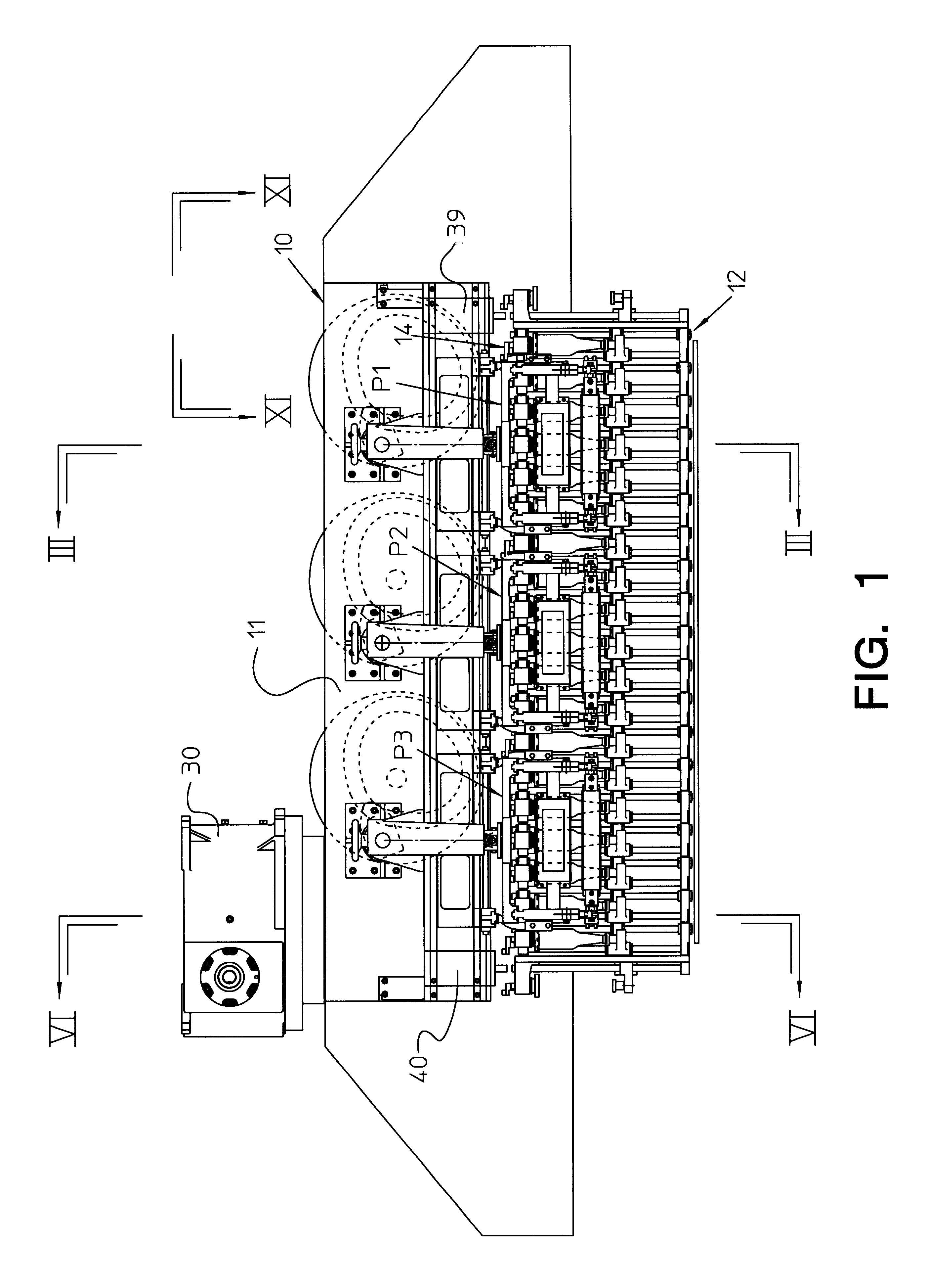
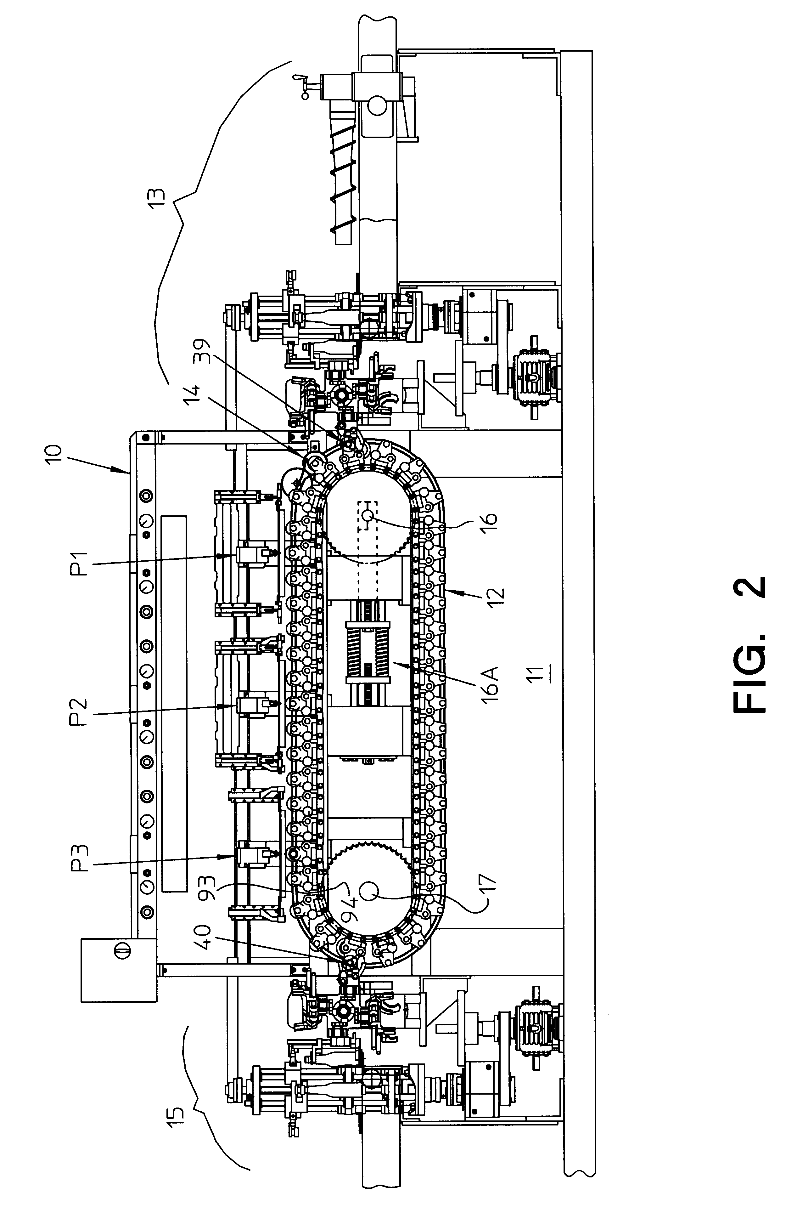
At each decorating station P1, P2 and P3 there are arranged a rotator assembly 51 embodying a construction of parts according to the present invention. As shown in FIGS. 4 and 9, the rotator assembly includes a rotator arbor 52 having an end portion formed with a slot opening 53 into which the drive roller 46 can pass into a driven relationship with crank arm 45 for rotating the bottle mounted on the workpiece carrier for a bottle decorating operation during a screen cycle. Arbor 52 is supported for rotation by spaced apart antifriction bearings mounted in a bearing housing 54 that is in turn supported by a face plate 55 secured to the base 11 of the decorating machine. In the embodiment shown in FIGS. 3-5, a one way clutch 56 is provided with an input drive gear 56A and a drive output sleeve 56B of the clutch is secured to an end portion of arbor 52 extending from the bearing housing 54. The arbor 52 extends outwardly beyond a sleeve 56B and secured to the terminal end portion ther...

second embodiment

FIGS. 18-21 illustrate bottle rotator which includes a tandem arrangement of an electrically actuated clutch 225, an electrically operated brake 226 and a position sensor assembly 227. The clutch 225 includes drive gear 225A mounted on a clutch hub controlled by a drive plate 225B which responds to a stationary coil 225C anchored on one side of a mounting plate 225D. The mounting plate 225D is secured to the pedestal 165. Gear rack 162 is positioned by the use of shims 165C into the desired meshing engagement with the teeth of gear 225A and held in place by bolts 165B. Brake 226 fitted in a cavity provided in pedestal 165 is anchored to the other side of mounting plate 225D. The position sensor assembly 227 is made up of a control block 228 clamped by a fastener bolt to the terminal end portion of arbor 52A and carries a reflective position indicator 229 rotated by the arbor 52A for impingement by a light sensor beam generated by a sensor 230 which also includes a detector to sense ...


PUM


Abstract

Workpiece rotators are constructed for decoration registration control in spaced apart decoration stations for bottles rotatably supported by carriers of an endless chain conveyor. A screen drive at each decorating station linearly reciprocates a decorating screen to decorate the bottle. A squeegee is positioned to maintain line contact between the decorating screen and a bottle for applying decoration during each screening cycle. The workpiece rotator is coupled by a drive controller to the screen drive to rotate a bottle synchronously with linear travel of the decorating screen. The drive controller uncouples the workpiece rotator from the screen drive at times other than the application of decoration to a bottle. In one embodiment electronic gearing is formed by a servo motor controlled by a scale moved by a screen drive along a detector head which provides an electrical signal used in a control system to maintain proper position of the servo motor during decoration, to re-home the rotator after decoration and to establish a predetermined power start-up position for the rotator. The vertical position of the rotator is adjusted for coaxial alignment between the rotational axes of the rotator and the workpiece. The drive for the rotator may include a one-way clutch or an electric clutch and brake driven by a pinion controlled by a rack in response to reciprocation of the screen drive.

Description

1. Field of the InventionThe present invention relates to an improved registration control in an intermittent motion type decorating machine for increasing the quality of printed indicia and precision of indicia registration on a workpiece and, more particularly, to improving the interrelationship and construction of drive components used for synchronously moving a decorating screen and a workpiece to apply decoration to workpieces especially to avoid registration errors in the placement of multicolor decorations in a given decoration area of a workpiece.2. Description of the Prior ArtAs shown in U.S. Pat. Nos. 2,231,535; 2,261,255; 2,721,516; 3,251,298; and 5,524,535 intermittent motion type decorating machines are known in the art and provide an indexing drive system to impart intermittent traveling motion to an endless chain conveyor used to supply workpieces such as containers made of glass or plastic. A container is moved by the endless chain conveyor through a predetermined di...

Claims


Application Information

Patent Timeline
Patent Type & Authority Patents(United States)
IPC IPC(8): B41F15/08
CPCB41F15/0872
Inventor MCCOY, GARY W.ZWIGART, JOHN M.STRUTZ, CARL J.TWEEDY, MARK R.
Owner CARL STRUTZ & CO
Learn More