Torches and burners for flame cultivation and flaming

a technology of flame burners and torch burners, which is applied in the direction of combustion types, ways, weed killers, etc., can solve the problems of heavy duty, large weight of torch burner heads, and limit as to possible cylinder sizes

Inactive Publication Date: 2001-07-10
D J BATCHEN
View PDF13 Cites 20 Cited by
  • Summary
  • Abstract
  • Description
  • Claims
  • Application Information

AI Technical Summary

Problems solved by technology

The main limitation as to possible cylinder sizes, however, will generally be their weight.
However, heavy duty, high capacity torch burner heads can have a substantial weight, eg 2 to 4 Kg.
Whilst this may not seem much, when mounted at the distal end of a long tubular torch handle of 1.5 m or longer, proper balancing of the torch head by an operator is often difficult and tiring.
Such type of arrangement and regulation has inherent weaknesses.
Firstly, and this is a well known phenomenon, regulating flow of a pressurised liquid fuel, which at ambient temperature is gaseous, by means of a flow regulator valve (for example, needle valve) will lead to partial vaporisation of the liquid either in the valve housing itself or downstream of the valve, with the associated take-up of heat by the vaporising resulting in cooling and possible freezing of the fuel lines and fitting.
If the flow velocity drop is substantial, the valve itself will tend to frost-up, the ebullition (boiling) temperature of propane fuel being around -42.degree. C.
A further drawback is the regulating process during steady state burner operation.
The burner / vaporiser torch of Pardee is essentially limited to work at operating pressures (gas pressure at the jet nozzle outlet) dictated by the storage pressure of the liquid LPG in its storage tank, as there is no means of adjusting the operating pressure and hence flame velocity subsequent to vaporisation of the fuel, as pressure drops within the vaporiser and burners are comparatively small.
Similar problems exist with the burner device with integrated fuel vaporiser disclosed in U.S. Pat. No. 5,030,086 (Jones)
Accordingly, manual adjustment of LPG flow into the vaporiser is superfluous (and non-efficient, see above).
The outlet or fuel delivery pressure at an LPG cylinder will remain about constant (assuming constant outside temperature and relatively small fuel flow rates compared with cylinder capacity) for as long as there remains a certain level of liquid LPG in the cylinder; after full vaporisation of liquid LPG in the cylinder, pressure drop will take place over a very short period of time, and torch operation will no longer be possible.
Whilst it is alternatively also possible to incorporate the first pressure reduction duct in the main body of the fuel delivery member, thereby providing an integral arrangement of metering duct and pressure reduction duct within the same part, the number of possible permutations of liquid fuel flow rate to gaseous fuel pressure reduction to achieve a desired torch operating regime, make this more problematic, mainly ease of manufacturing considerations make a multi-part construction of the fuel delivery member of the torch desirable.

Method used


Image

  • Torches and burners for flame cultivation and flaming
  • Torches and burners for flame cultivation and flaming
  • Torches and burners for flame cultivation and flaming

Examples


Embodiment Construction

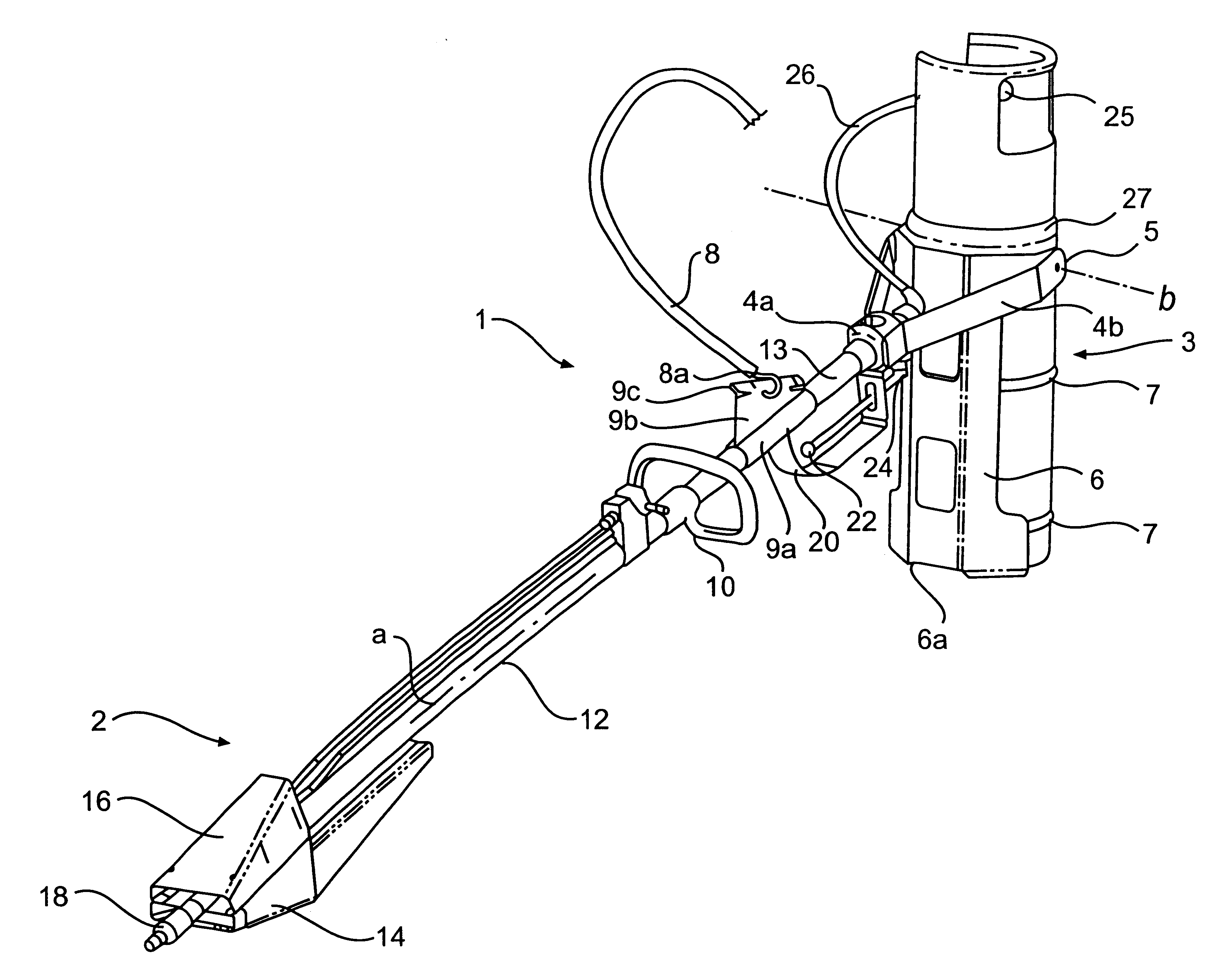
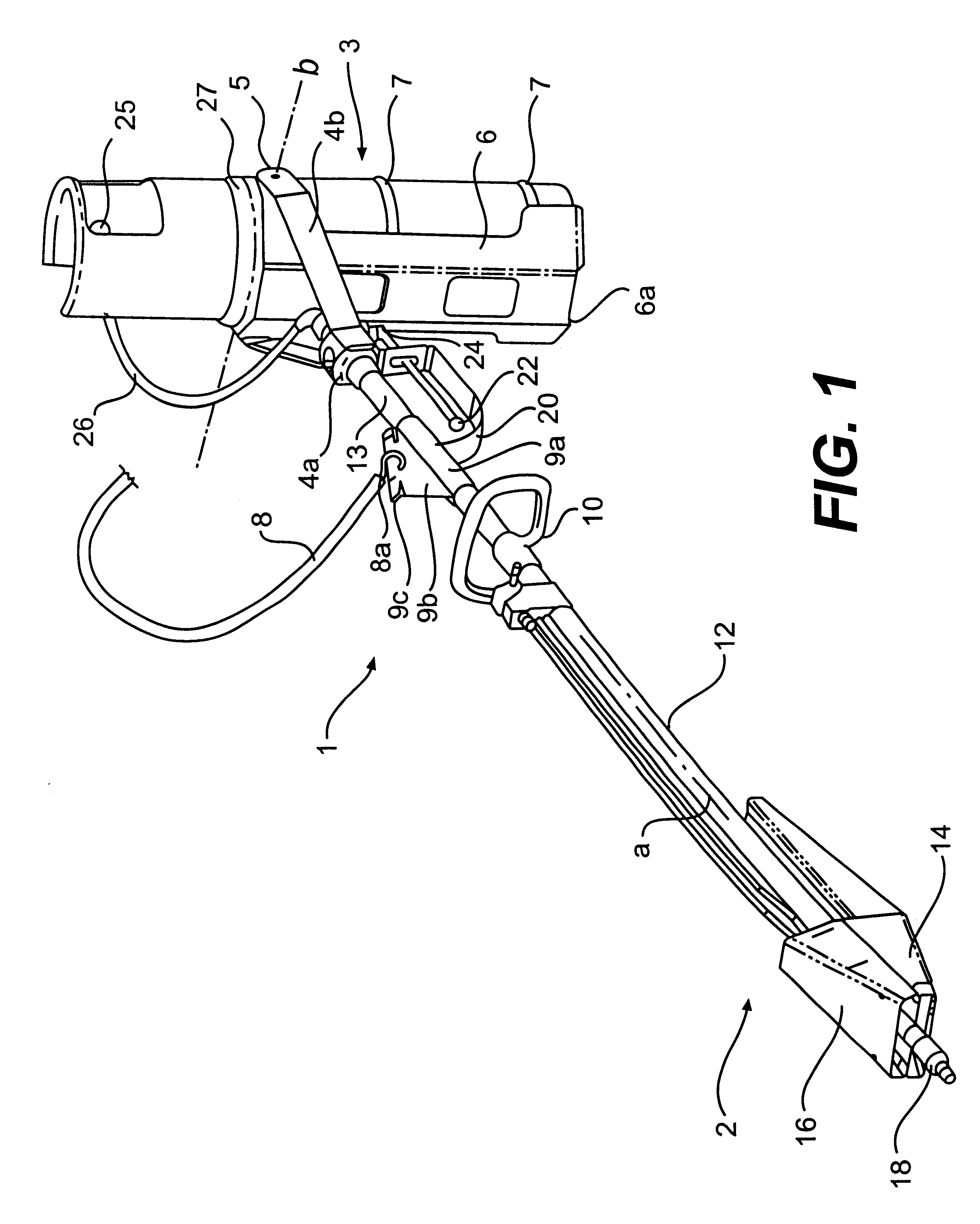
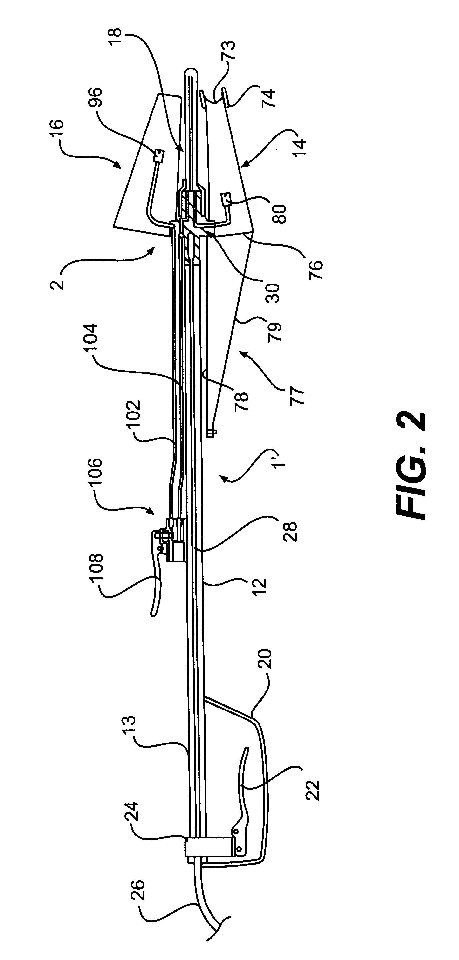
Referring to the drawings, first to FIGS. 1 and 2, there is illustrated two variants of a hand-held, flaming torch 1 and 1' which use LPG as fuel source and which can be used in numerous applications, such as for flame cultivation of terrain that is inaccessible to larger, tractor-carried flame cultivator torch batteries, weeding of irrigation channels, burning of tree stumps, softening of bitumen surfaces for road works, spot back burning operations during forest fires and other applications which require localised application of a flame or high heat.

Torch 1 of FIG. 1 has two main structures, a torch head generally indicated at 2 and a fuel tank mounting structure, generally indicated at 3, whereas torch 1' of FIG. 2 lacks the fuel tank mounting structure, as the fuel supply cylinder for torch 1' is to be carried separately from the torch, either using a customised back pack or a non-motorised cart (not shown) as is known in the art.

A straight, aluminium or light weight metal or co...


PUM


Abstract

The invention relates to an LPG combusting burner device for flaming and flame cultivation purposes and an improved hand-held torch that may incorporate such burner device. The burner device includes a primary burner (14) having at least one fuel delivery nozzle or jet (80) arranged within an open combustion chamber (71) defined within a burner skirt (70) such as to direct a stream of fuel towards a flame delivery opening of the skirt (70), and a vaporiser (18) located in heat exchanging proximity to the primary burner (14) and having a pressurization chamber with an inlet for liquid LPG fuel and an outlet for gaseous LPG fuel, the inlet being arranged to be in fluid communication with a source of pressurized LPG and the other being in communication with the nozzle of the primary burner. A metering duct (37) is located in close vicinity or within the vaporiser (18) and arranged to discretely limit the amount of liquid fuel entering the vaporisation chamber via its inlet, and a first pressure reduction duct (52) is provided in the flow path of gaseous fuel between the vaporisation chamber outlet and the nozzle of the primary burner (14) the first pressure reduction duct (52) arranged to impart a discrete pressure drop to gaseous fuel flowing therethrough between the vaporisation chamber (50) and the nozzle of the primary burner (14), the discrete pressure drop being such as to generate a low velocity combustion flame in the primary burner (14) during normal burner operation.

Description

The present invention is concerned with flame cultivation burners and flaming torches which find application in agricultural and forrestal land management, road surface asphalting and similar tasks which require application of heat or a flame onto objects. In particular, the present invention is concerned with flame cultivation burners and flaming torches which use liquefied petroleum gas (LPG) as a fuel source for the bumers, and relates to an improved burner with integral fuel vaporiser and improved hand-held flame cultivation and flaming torches.BACKGROUND OF THE INVENTION AND PRIOR ARTFlame treatment or "flame cultivation" is well known in agriculture and horticulture to control weeds and pests that adversely affect arable land. There is a large body of published patent literature concerned with many aspects of this technology, U.S. Pat. No. 2,408,328 setting forth the basic principles of flame cultivation, and thus, reference should be made to this U.S. patent for a detailed ex...

Claims


Application Information

Patent Timeline
Patent Type & Authority Patents(United States)
IPC IPC(8): A01M21/04A01M21/00A01M15/00F23D11/44F23D11/36
CPCA01M15/00A01M21/04F23D14/66F23D14/38F23D14/28Y02E20/34
Inventor JOHNSTONE, IANSMITH, ROBERT
Owner D J BATCHEN
Why Eureka
Try Eureka