
Micro-electrophoresis chip for moving and separating nucleic acids and other charged molecules

a micro-electrophoresis and chip technology, applied in the direction of isotope separation, diaphragm, electrophoresis, etc., can solve the problems of insufficient detection sensitivity of detectors, inability to develop methods or apparatus for using electrophoresis in conjunction with recently developed miniature components for analyzing biomolecules, and insufficient sensitivity of small electrophoresis apparatuses such as the 43.times.50.times.0.45 mm

Inactive Publication Date: 2001-07-17
SIEMENS HEALTHCARE DIAGNOSTICS INC +1
View PDF20 Cites 81 Cited by
  • Summary
  • Abstract
  • Description
  • Claims
  • Application Information

AI Technical Summary

Problems solved by technology

Though electrophoresis is a well studied phenomena, researchers have not developed methods or apparatus for using electrophoresis in conjunction with recently developed miniature components for analyzing biomolecules.
Small sized electrophoresis apparatus such as the 43.times.50.times.0.45 mm gels of the PhastSystem of Pharmacia Biotech (Uppsala, Sweden) do not offer enough sensitivity for the micromanipulation of tiny samples of charged molecules.
Thus, electrodes which are required for a certain application may be turned on, while unnecessary ones may simply be turned off.
The main issue in the selection of the electronic detectors as with optical and radioactive detectors, is whether the sensitivity of the detector is sufficient to detect the passage of the charged molecule through the solvent film.

Method used


Image

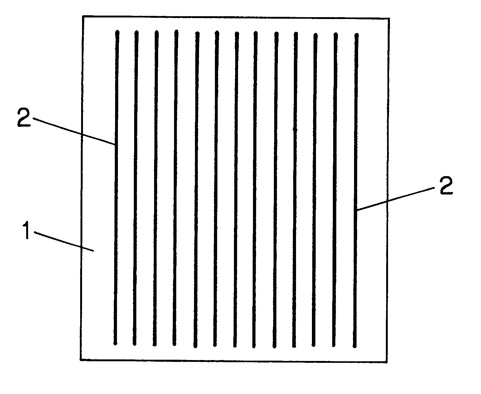
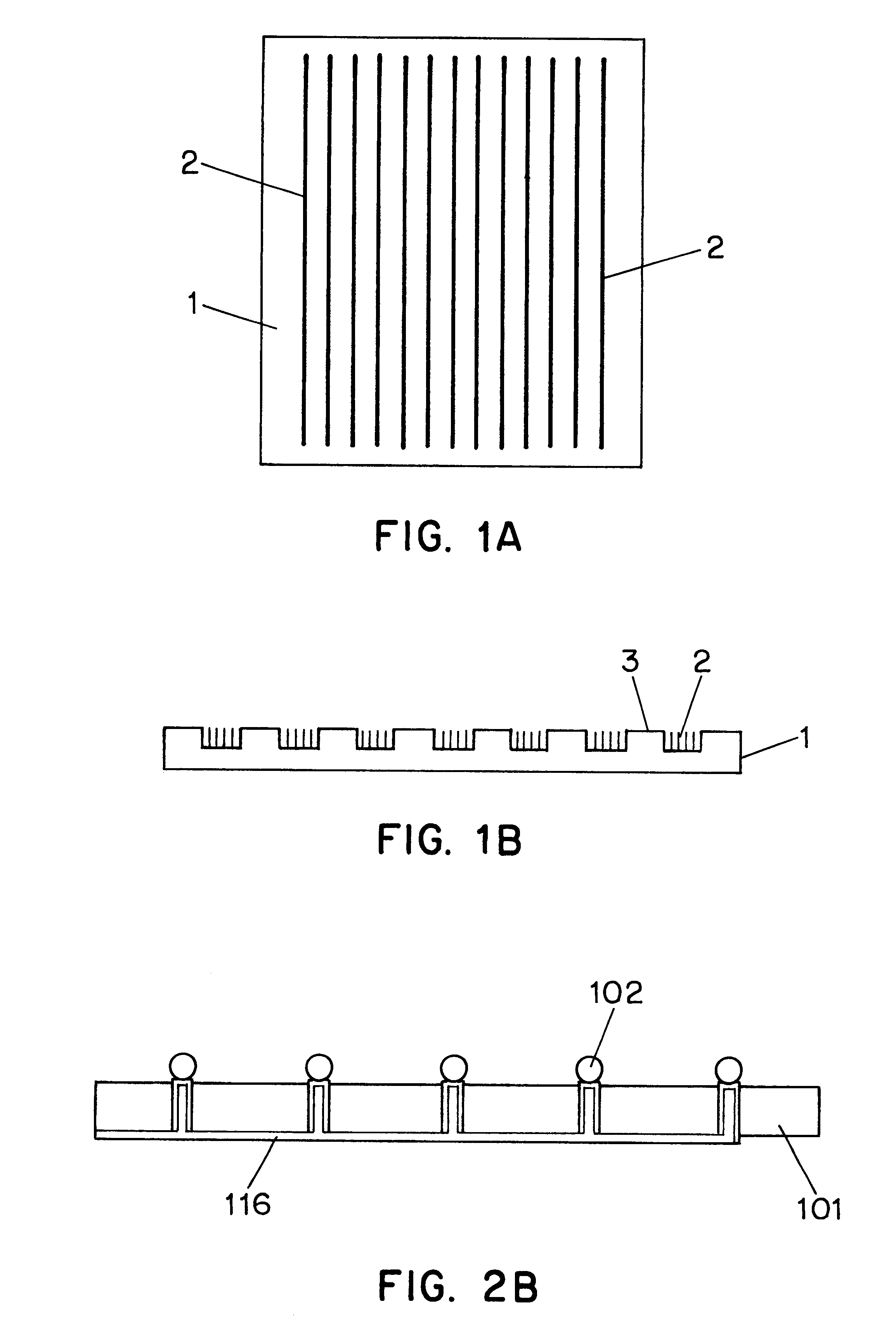
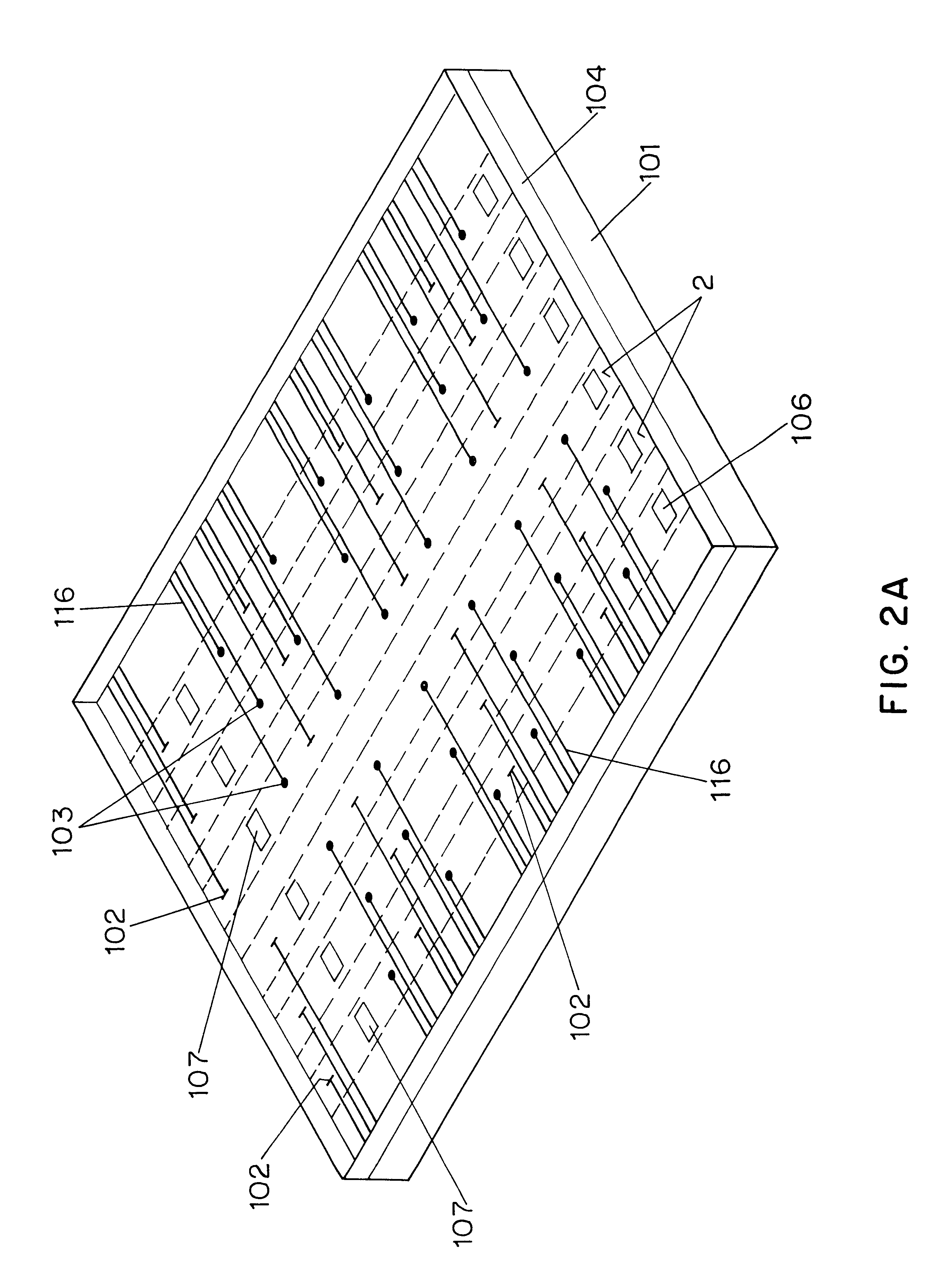
  • Micro-electrophoresis chip for moving and separating nucleic acids and other charged molecules
  • Micro-electrophoresis chip for moving and separating nucleic acids and other charged molecules
  • Micro-electrophoresis chip for moving and separating nucleic acids and other charged molecules

Examples


example 2

In a two substrate system, small nucleotide fragments are separated from large fragments by switching the charges on electrodes during the course of electrophoresis. In FIGS. 9A-9C, the sample, 701, is loaded through the loading site, 702, into the separation matrix, 703, by a capillary pipettor, 704. As it is in a horizontal format, the loading site is gently topped up with buffer after the sample is loaded. Electrophoresis begins with the voltages between micro-electrodes, 705, as shown in FIG. 9A. After a short period of time, FIG. 9B, the sample separates into species, 706, with the smallest fragments moving the fastest, and electrophoresis is stopped. When electrophoresis restarts, FIG. 9C, the voltages across the electrodes are changed, such that fragments on one side of a break point, 708, are drawn in one direction, while fragments on the other side are drawn in another direction, as indicated by the arrows. An apparatus as noted may require a detector (not shown) to determi...

example 3

A further advantage of the instant invention, is the ability to move samples from one well to another for different treatments, such as in an integrated DNA diagnostic chip. As described in U.S. patent application Ser. Nos. 08 / 271,946 and 08 / 271,942 which are incorporated herein by reference, the most cost effective means of DNA diagnosis involves a hierarchical method of testing, wherein a series of analyses of increasing accuracy are employed to diagnose the presence or absence of genetic mutation. It is possible to integrate all the hierarchical steps on one chip, as illustrated in FIG. 10. FIG. 10 shows an integrated DNA diagnostic chip which uses the diagnostic method of the above noted patent application. A highly simplified discussion of the steps involved in the hierarchical method is provided below. In the first step, a group of exons of a gene to be diagnosed is examined for insertion and deletion mutations. In a reaction tube (not shown) the suspect exons of the patient a...

example 4

Research has shown that DNA, like other semi-rigid polymers in high concentration, has a natural tendency to form a liquid crystal at approximately 250 mg / ml. (Strzelecka T E; Davidson M W; Rill R L; Multiple liquid crystal phases of DNA at high concentration; Nature 1988; 331: 457-60; Rill R L; Liquid crystalline phase in concentrated aqueous solutions of Na+DNA. Proc. Natl. Acad. Sci. USA 1986; 83(2) 342-6). An embodiment of the invention suitable for running on the microelectrophoresis (2-10 micron) chip relies on the birefringent properties of DNA in a liquid crystal state.

Ultrathin layers of liquid crystals are routinely employed in the liquid crystal display industry. In certain orientations, liquid crystals have birefringent properties that cause substantial rotation of light and cause easily detectable light effects. Adapting this methodology to detection of DNA, it is observed that DNA in liquid crystal state acts as a birefringent material that will cause a substantially g...


PUM

PropertyMeasurementUnit
depthaaaaaaaaaa
lengthaaaaaaaaaa
lengthaaaaaaaaaa

Abstract

A microelectrophoresis chip comprises a substrate in which there are formed one or more channels, one channel for each sample to be evaluated. The channels extend for the length of the chip, a distance of generally around 1 cm, and are about 1 to 10 mum wide and 1 to 10 mum in depth. The channels are filled with a homogeneous separation matrix which acts as an obstacle to the electrophoretic migration of the charged molecules. Microelectrodes disposed in the channels are used to induce an electric filed within the homogeneous separation medium. When a voltage is applied across two or more of the microelectrodes, the charged molecules are induced to move and separate according to the electric field density, the type of solvent film, and the charge, shape and size of the charged molecule. The chip may further comprise detectors, such as light polarization detectors, fluorescence emission detectors, biosensors, electrochemical sensors or other microcomponents which may include sites for enzymatic or chemical manipulation of the moved or separated charged molecules.

Description

BACKGROUND TO THE INVENTIONThe instant invention relates to methods and apparatus for electrophoretic movement and separation of samples of charged molecular species in a microelectrophoresis chip.The principle of separating a mixed pool of charged molecules into separate species by electrophoresis through which a separation matrix is well known in the art. Commercial apparatus are available for separation of proteins, nucleic acids and other biomolecules. In the most general format, a sample of biomolecules is loaded into a separation matrix (e.g., agarose gels and polyacrylamide gels, either with or without denaturing buffer solutions) at a loading site. Electrodes, e.g., solution electrodes, are placed at either end of the separation matrix. An electric field is the applied across the separation matrix, which causes electrically charged molecules in the sample migrate away from the loading site. The direction and extent of sample migration is a function of charge, size and shape ...

Claims


Application Information

Patent Timeline
Patent Type & Authority Patents(United States)
IPC IPC(8): G01N27/447C12N15/09B82B1/00C12Q1/68G01N33/50G01N33/58
CPCG01N27/44704G01N27/44791G01N27/44773
Inventor YAGER, THOMAS D.WATERHOUSE, PAULIZMAILOV, ALEXANDRE M.MARUZZO, BRUNO C.STEVENS, JOHN K.LARSON, MARINA T.
Owner SIEMENS HEALTHCARE DIAGNOSTICS INC
Learn More