Method and equipment for offshore oil production with primary gas separation and flow using the injection of high pressure gas

Inactive Publication Date: 2001-07-31
PETROLEO BRASILEIRO SA (PETROBRAS)
View PDF13 Cites 18 Cited by
  • Summary
  • Abstract
  • Description
  • Claims
  • Application Information

AI Technical Summary

Benefits of technology

The object of this invention is to provide equipment and a method to assist flow

Problems solved by technology

In the flow of oil, as occurs in undersea production lines, large pressure head losses occur due mainly to the large simultaneous flows of gas and oil, and which give rise

Method used


Image

  • Method and equipment for offshore oil production with primary gas separation and flow using the injection of high pressure gas
  • Method and equipment for offshore oil production with primary gas separation and flow using the injection of high pressure gas
  • Method and equipment for offshore oil production with primary gas separation and flow using the injection of high pressure gas

Examples


Example

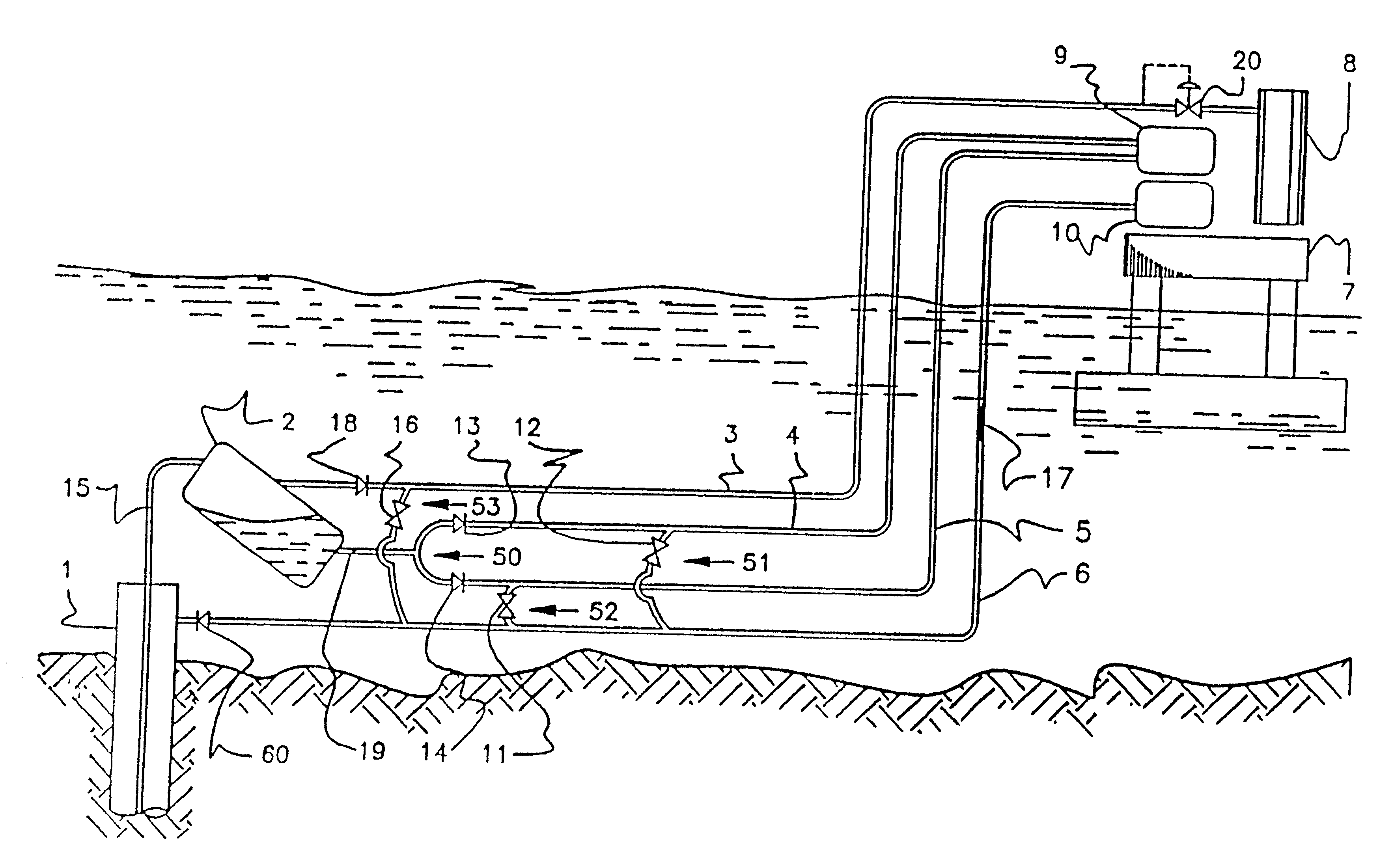
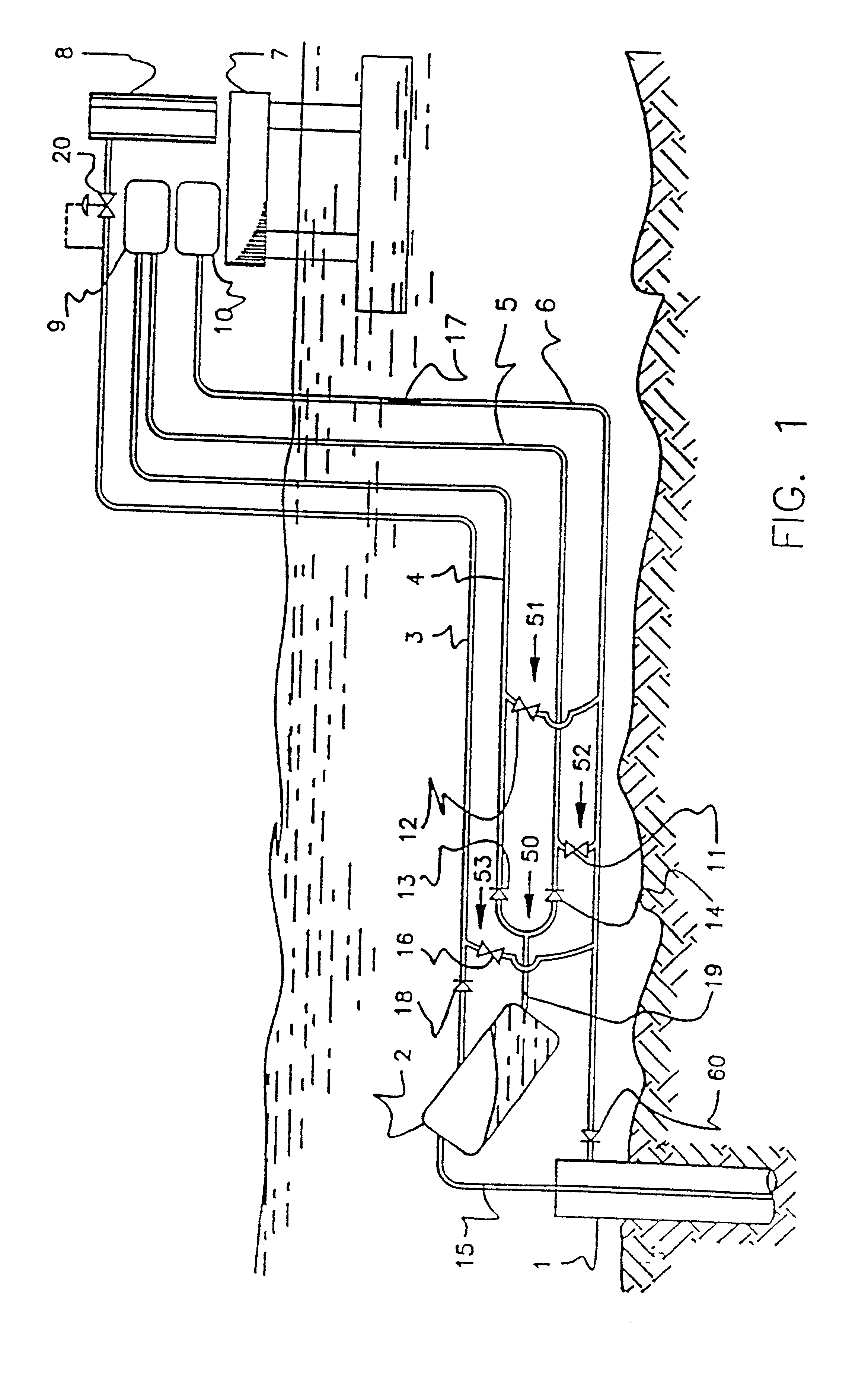
FIG. 1 shows a diagrammatic representation of an embodiment of the equipment according to this invention, in which two lines 4 and 5 are used to effect flow of the liquid phase of the fluids produced by an offshore oil well to a gathering center. In this embodiment the fluids are collected in a surge tank 9 located on a platform 7 serving as the gathering center.

A wellhead 1 of an offshore well is connected through a wellhead flow line 15 to the top of an undersea separating means, shown in FIG. 1 as a subsea primary separating vessel 2, the function of the separating means being to effect primary separation of the liquid and gas phases of the fluids produced by the offshore oil well.

A pressurized gas line 6 connects an annulus of the offshore well to a compressed gas supply system 10, which in this embodiment is located on a platform 7. A pressurized gas check valve 60 is fitted in the pressurized gas line 6, close to the wellhead 1. The purpose of this pressurized gas check valve ...


PUM


Abstract

A subsea primary separating vessel (2,22) is installed close to the wellhead (1,31) of an oil producing well to effect primary separation of the liquid and gas phases of the fluids produced. A line (3,23) connected to the top of the separating vessel allows separated gas to flow to a gathering vessel (8,28) located at any gathering center. At least one flow line (4,5,24) connects the lower part of the separating vessel to a vessel (9,29) located at any gathering center. When the volume of liquid phase which separates out within the at least one flow line begins to exert a back pressure which adversely affects production from the well, pressurized gas can be injected into the flow line(s) for a specific period of time in order to promote the flow of liquid gas to the vessel (9,29). If it is desired that flow efficiency should be increased a mechanical interface driven by the pressurized gas may be used to encourage flow of the liquid phase.

Description

This application is the national phase of international application PCT / GB97 / 01200 filed May 1, 1997 which designated the U.S.Field of the InventionThis invention relates to a method and equipment to assist the flow, up to the surface, of hydrocarbon mixtures containing a high gas concentration. It may be applied to a single offshore oil well or to an undersea gathering line (manifold) which receives production from various wells for subsequent delivery.In the flow of oil, as occurs in undersea production lines, large pressure head losses occur due mainly to the large simultaneous flows of gas and oil, and which give rise to great shear stresses in the flow.In the technique of deep offshore production another factor which gives rise to high pressure gradients is the great difference in level between the wellhead and the platform, which very frequently makes it necessary to use extensive vertical pipes to deliver the products to the surface; such pipes are known to those skilled in t...

Claims


Application Information

Patent Timeline
IPC IPC(8): E21B43/01E21B43/00E21B43/12
CPCE21B43/121E21B43/01E21B43/122
Inventor LIMA, PAULO C. R.
Owner PETROLEO BRASILEIRO SA (PETROBRAS)
Why Eureka
Try Eureka