Boring apparatus with coupling for rapid connection of drill string segments

a technology of drilling string and coupling, which is applied in earth drilling, drilling machines and methods, construction, etc., can solve the problems of unnecessarily time-consuming, large excavation or launch pit, and large space requirements, and achieves low specific gravity, reduced opening cross-section, and light pipe length

Inactive Publication Date: 2001-07-31
TRACTO TECHN PAUL SCHMIDT SPEZIALMASCHEN
View PDF12 Cites 6 Cited by
  • Summary
  • Abstract
  • Description
  • Claims
  • Application Information

AI Technical Summary

Benefits of technology

The locking portion is preferably provided with at least one key face for non-rotatably fixing the string section as the next following string section is screwed on. The locking portion can further include a stop face, and a tubular filler body of a material of relatively low specific gravity, for example of plastics material, may be located in the interior of the string section. This filler body serves to reduce the cross-section of the opening of a tubular drill string to the appropriate size for passage of a flushing, cutting, lubricating or steering liquid, and in view of its relatively low specific gravity, to keep the total weight of the pipe length as light as possible.

Problems solved by technology

However, it requires a considerable amount of space and, for example in the case of horizontal boring, needs a correspondingly large excavation or launch pit.
As a result of the length of the frame the known apparatus requires a large excavation or launch pit.
This requires a double screwing operation for each section of the string and therefore is not only unnecessarily time-consuming but also increases the space required, since the distance between the drive shaft on the one hand and the rearward end of the drill string on the other hand must be greater than the length of a string section.
A further disadvantage of the known boring apparatus is that before the addition of a new section to the string the drive shaft must be unscrewed from the internal thread at the end of the drill string while the drill string is held fast by means of expensive auxiliary units to enable the screw thread of the drive shaft to be unscrewed from the end of the drill string.
The above-mentioned disadvantages are also suffered by a boring apparatus known from German patent 41 22 350, which needs so much space that it is mounted above ground and first creates a downwardly inclined pilot bore in order to reach the laying depth and then continues boring horizontally.
However, such apparatus is not suitable for laying house connections, since on account of its large external dimensions it cannot be accommodated in the sidewalk region.
Furthermore it is not possible even to reach the laying depth in the sidewalk region in order to connect the house connection to a main line laid along the street.

Method used


Image

  • Boring apparatus with coupling for rapid connection of drill string segments
  • Boring apparatus with coupling for rapid connection of drill string segments
  • Boring apparatus with coupling for rapid connection of drill string segments

Examples


Embodiment Construction

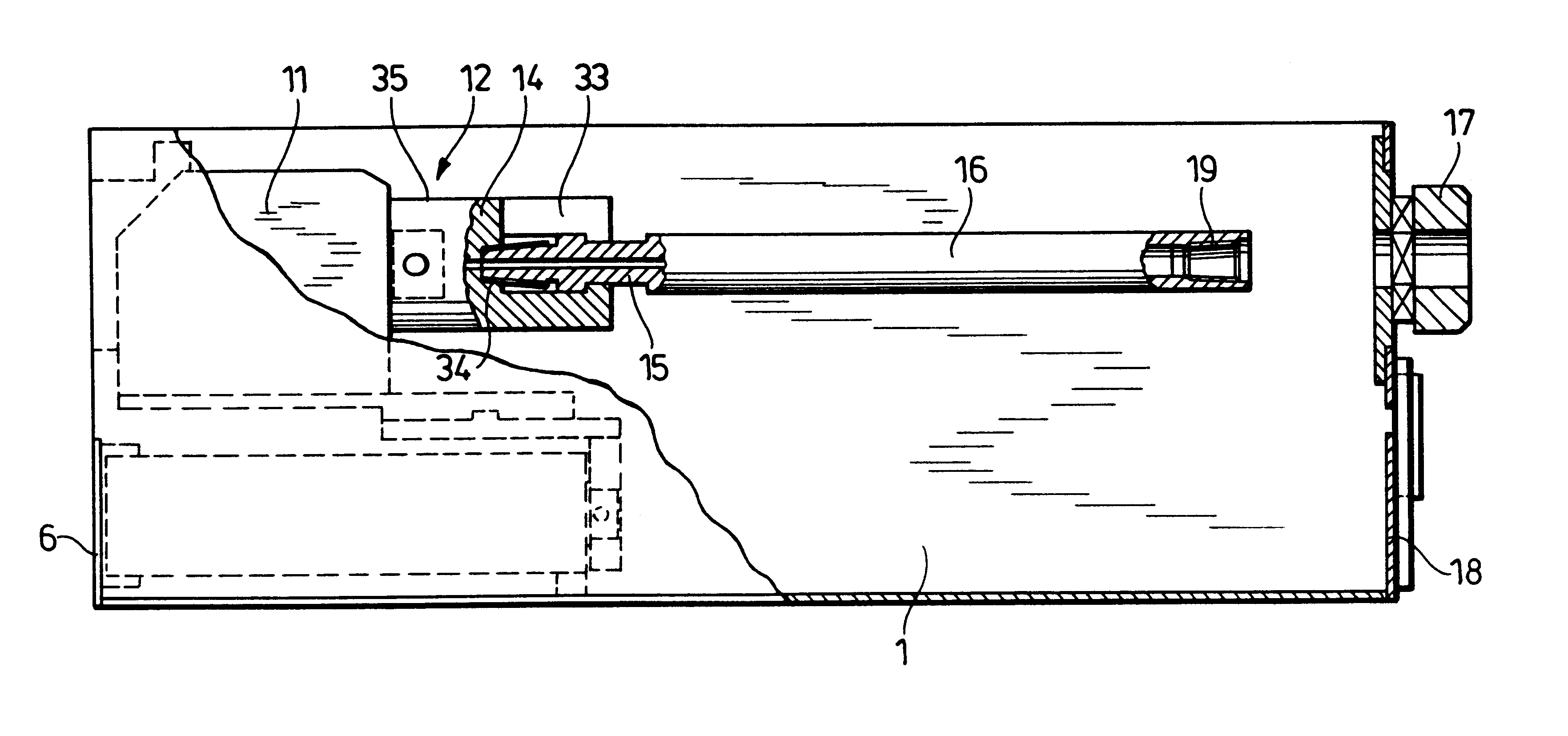
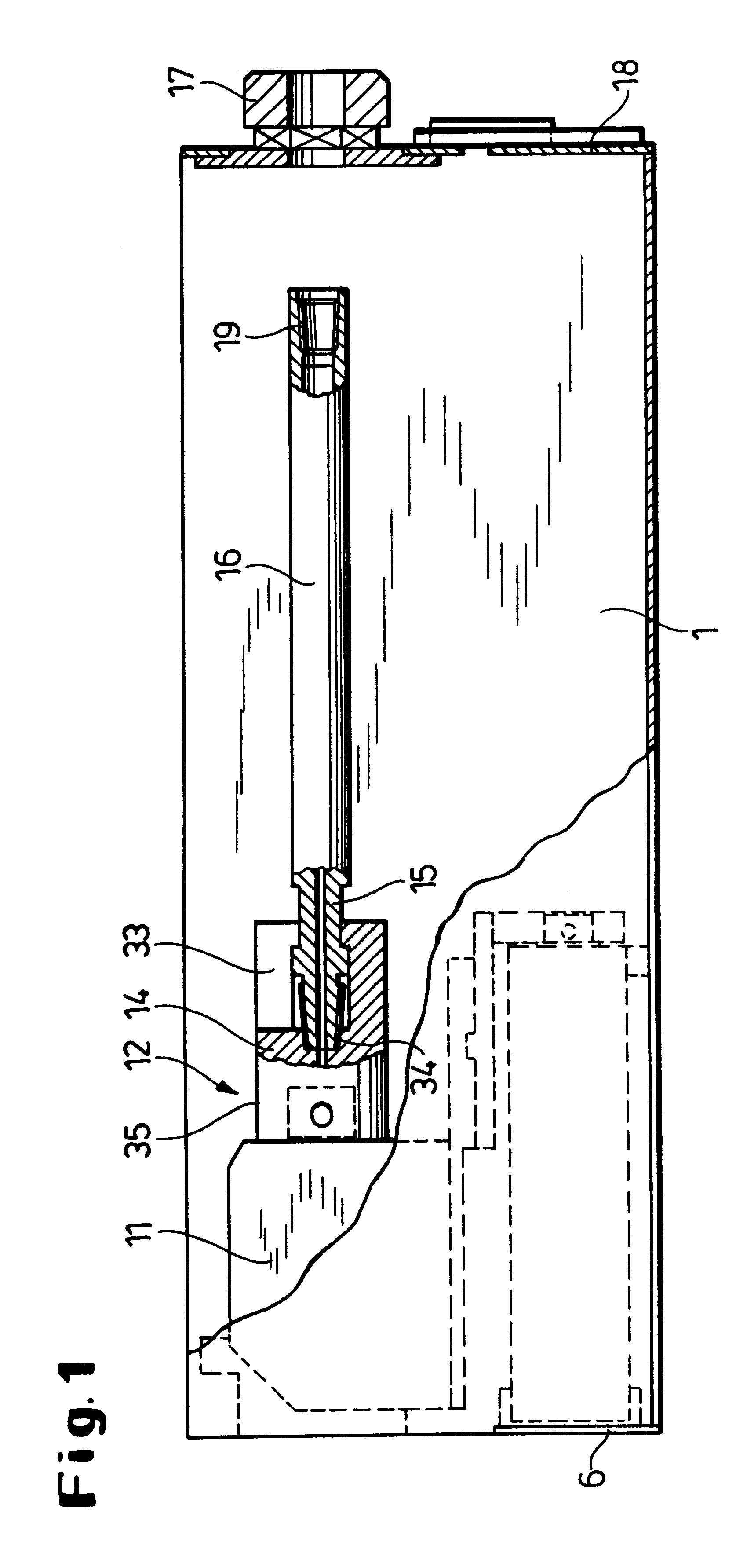
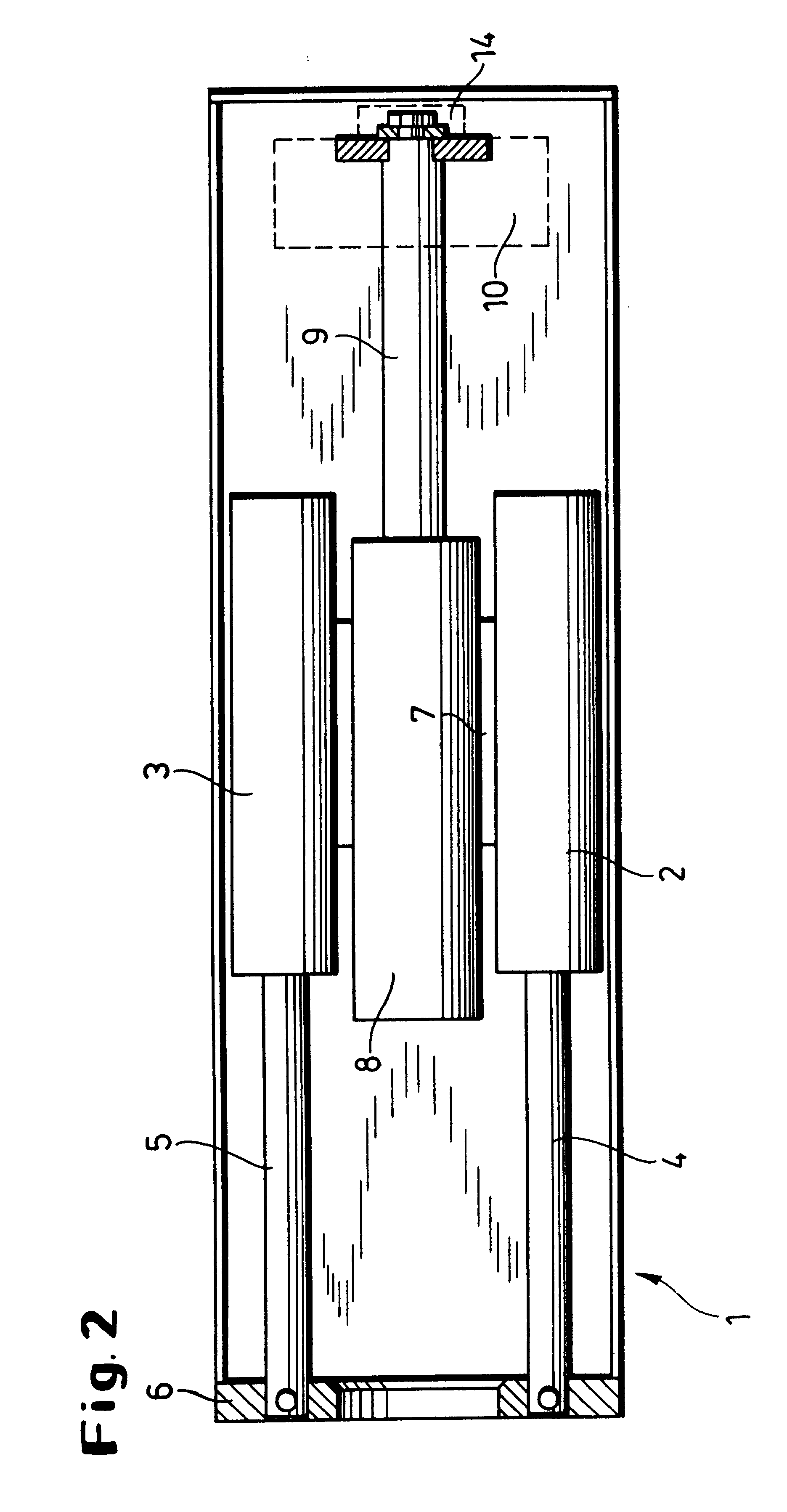
The apparatus 50 illustrated comprises a box-shaped frame 1 in which two thrust cylinders 2, 3 are mounted parallel to one another on a sliding carriage (not shown) with their piston rods 4, 5 supported on the rear end wall 6 of the housing 1. The two hydraulic cylinders 2, 3 are connected rigidly together by a bar 7 on which a further cylinder 8 is mounted in the middle. The piston rod 9 of the middle cylinder 8 carries a console 10, shown only schematically, on which a rotary drive 11 is mounted.

The drive shaft (not shown) of the rotary drive 11 is non-rotatably connected to a plug connection 12 consisting of a chuck 14 and a locking portion 15 at the end of a string section 16. The string section 16 is aligned with a string guide 17 on the front end wall 18 of the frame 1 and is provided at its forward end with a slightly conical screw coupling 19 having an internal screw thread 20, which can be screwed on to the rearward end of a preceding first section, for example having a dri...


PUM


Abstract

In apparatus for producing and expanding earth boreholes and for destroying and replacing underground pipelines or for driving in pipes, a feed drive and a rotary drive having a plug-in coupling comprising a chuck and a locking portion at the end of a string is located in a frame. The string comprises a plurality of sections or lengths having an internal screw thread at one end and an external screw thread on the locking portion at the other end, which at the same time is provided with a key face to hold fast said string section while it is screwed together with the next following string section.

Description

The invention relates to apparatus for producing and expanding earth boreholes and for destroying and replacing underground pipelines or for driving in pipes.BACKGROUND AND PRIOR ARTApparatus of this kind is known and has often proved its worth in practice. However, it requires a considerable amount of space and, for example in the case of horizontal boring, needs a correspondingly large excavation or launch pit.A boring apparatus for destructive replacement of an underground pipeline is known, for example, from U.S. Pat. No. 4,507,019. This apparatus comprises a frame with an adjustable mounting for two feed cylinders connected to a sliding carriage. Mounted on the carriage is a rotary drive of which the horizontal shaft is provided with an external screw thread and can be screwed on to the internal screw thread at the rearward end of a drill string made up of a number of sections. As a result of the length of the frame the known apparatus requires a large excavation or launch pit....

Claims


Application Information

Patent Timeline
Patent Type & Authority Patents(United States)
IPC IPC(8): E21B7/30E21B7/00E21B19/086E21B19/00E21B19/08E21B19/16
CPCE21B19/086E21B7/30
Inventor PUTTMANN, FRANZ-JOSEFBALVE, GERHARD
Owner TRACTO TECHN PAUL SCHMIDT SPEZIALMASCHEN
Why Eureka
Try Eureka