
High efficiency light source utilizing co-generating sources

a co-generating source and high-efficiency technology, applied in the direction of gas-filled discharge tubes, incadescent envelopes/vessels, electric discharge lamps, etc., can solve the problems of limiting the applicability of gas lanterns, requiring precision optical focusing, and the design of coated incandescent filaments does not improve on the use of reflective filters to regenerate wasted energy, etc., to achieve high optical filter substrate shape stability and accuracy, low thermal capacity structure, and sufficient structural temperature stability

Inactive Publication Date: 2001-07-31
STARK DANIEL LEE
View PDF13 Cites 18 Cited by
  • Summary
  • Abstract
  • Description
  • Claims
  • Application Information

AI Technical Summary

Benefits of technology

(b) act as a larger target to receive and recycle the discriminative filter reflected energy for light regeneration, thus providing for a relaxed form for the reflective filter substrate,
An object of this invention is to provide a mirrored polarizing filter that is used to reflect the unpolarized wasted components of the incandescent radiation back to the filament-mantle or fluorescent coating as in the case of fluorescent lights. The advantage is improved efficacy for a incandescent linear polarized light source because the potentially wasted 97% energy is reflected back for recycling.

Problems solved by technology

(1) The coated incandescent filament design does not improve on usage of reflective filters to regenerate the wasted energy because the target filament remains a small target requiring accurate focusing of the reflected radiation.
The disadvantage of these prior arts is restricting applicability to gas lanterns.
No prior art was identified that describes utilization of existing low thermal capacity insulators as a method to improve efficacy for electric lamps.
However, the ellipsoidal shape is an alternate shape still requiring precision optical focusing.
All of the patents restrict the energy recycling by focusing the wasted energy back to the originating small tungsten incandescent filament.
Successful precise aiming of wasted radiation energy onto the tungsten filament does not fully capture the energy because the coiled tungsten incandescent filament is not a solid body, but a coiled spring that has gaps between the coils.
A prior art disadvantage is the requirement that the reflecting substrate supporting the discriminative filter conform to an optically precise form sufficiently accurate to focus the wasted energy back to the small incandescent filament.
Because of the strict focusing accuracy, the prior art's focusing geometry is limited to spherical, tubular, ellipsoidal or lens shaped envelopes with the tungsten filament at the precise focus.
The required precision makes the filter uneconomical and impractical.
If the focal point misses the filament, the energy is lost to lamp heating, and in may cases lamp base heating.
A typical coiled filament in a PAR (parabolic aluminized reflector) lamp increases length by approximately 20% when heated, causing significant filament sag.
A design disadvantage is that it does not accommodate filament warping.
Thus any heat induced sagging or warping moves the filament from the tube's center apex, causing reflected energy to miss the incandescent filament, and causing a lamp temperature increase.
The filament continues to warp with usage causing energy recycling efficiency degradation.
Another disadvantage is the filter's temperature survivability requirement that requires the filter material to be at some distance from the incandescent filament to avoid overheating.
As the filament warps, parts of the filament approach the discriminative filter, causing local hot spots that damage the discriminative filter.
If the filter is mounted on the exterior, any contamination from handling or dust settling on the lamp also causes local heating which damages the filter, and adds to further heating and filter damage.
There is therefore a tradeoff between efficiency and the self supporting requirements which determine life-span and shock resistance.
The reflectors form a forward projected beam shape, but undesirably act to reflect some energy toward the lamp base.
The spherical precision focusing configurations that concentrate the discriminative filter reflected energy onto one place on the filament causes excessive heating at that point, which forms a weak spot and causes filament failure.
The patents restrict their applicability to wavelength bands.
This application was not previously practical because of the prior art's stringent focusing accuracy requirements.
The precise cylindrical, spherical and ellipsoidal shapes with the filament in the focal point are no longer the only practical designs.

Method used


Image

  • High efficiency light source utilizing co-generating sources
  • High efficiency light source utilizing co-generating sources
  • High efficiency light source utilizing co-generating sources

Examples


Embodiment Construction

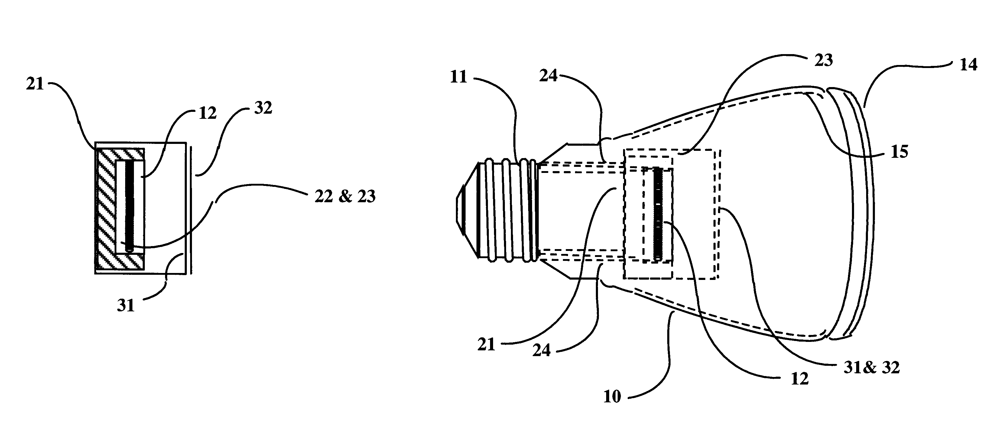
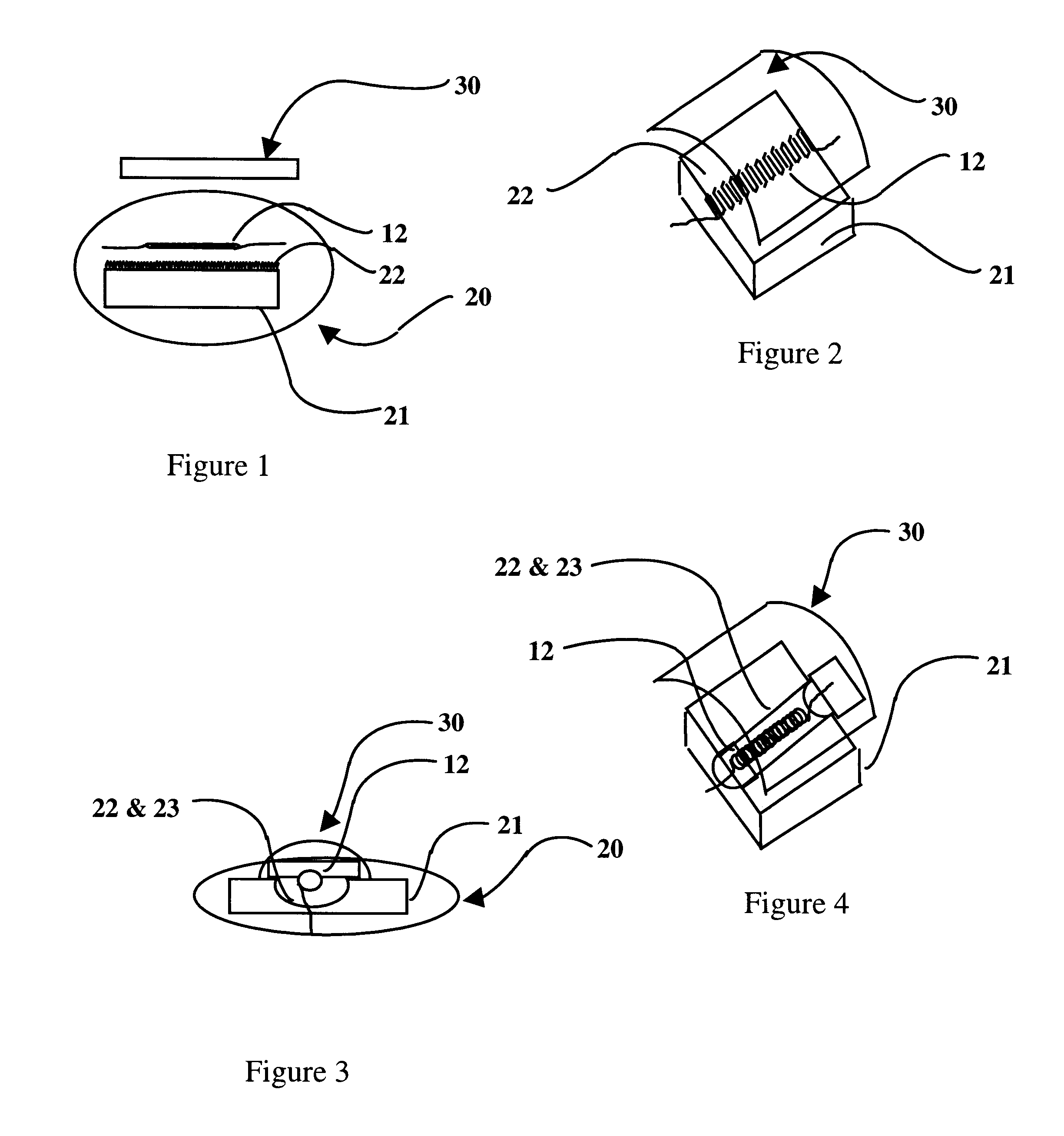
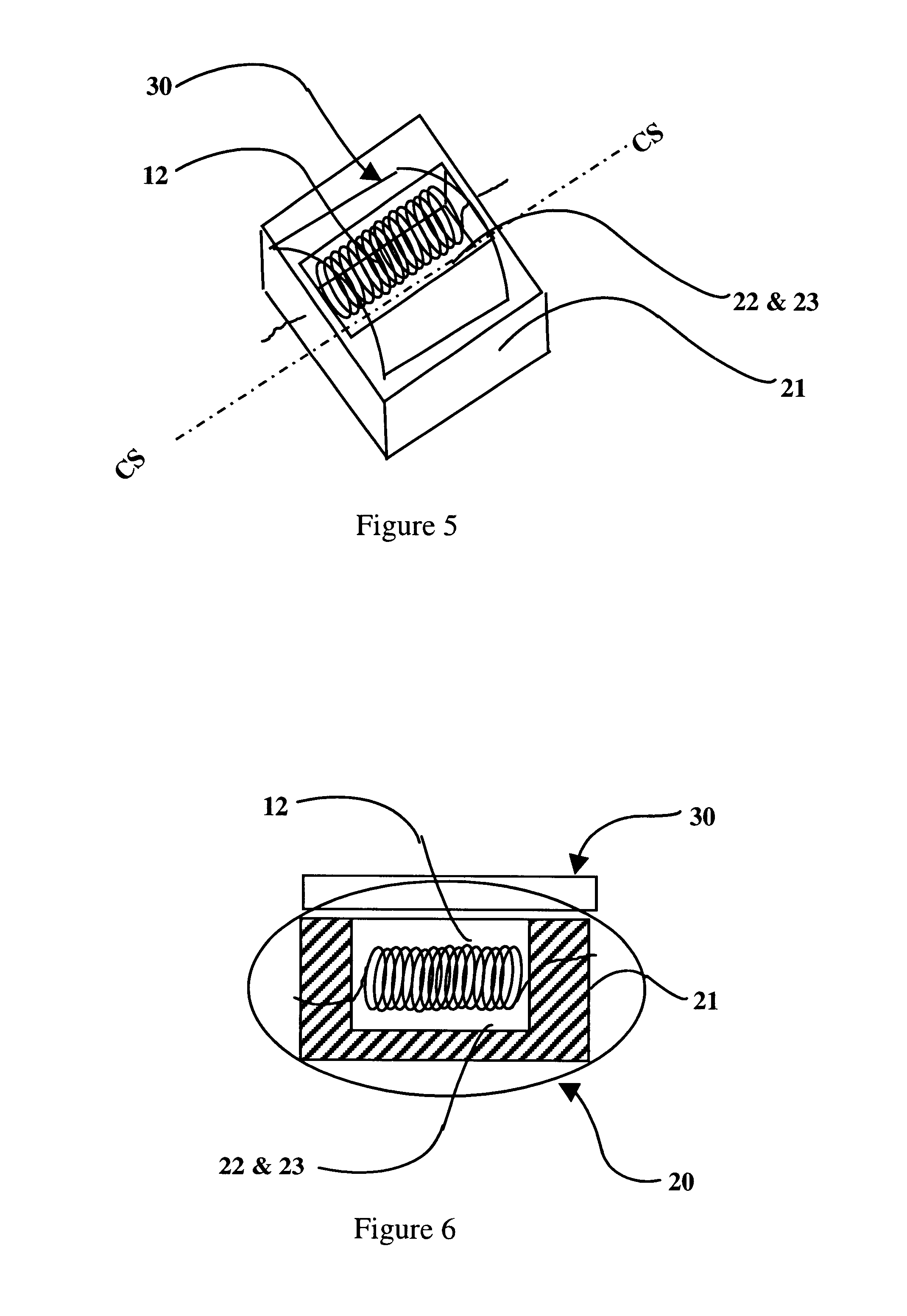
There are several main objects to the present invention which improves the efficacy and the chromatic quality of the conventional incandescent lamp designs. These objects are use of a (1) low thermal capacity, high efficiency insulator, (2) use of candoluminescent materials as a secondary emission source, and (3) use of a mirrored polarized filter. These objects are integrated to provide (4) an efficacy improved manufacturable lamp design that requires less stringent accurate reflector shapes as compared to the prior art's requirements. These main objects are discussed below.

1. CANDOLUMINESCENT MANTLE, ITEM 22

The mantle is composed of candoluminescent material that will emit desirable wavelengths when heated and act to provide a secondary light source in addition to the incandescent filament. The mantle provides a larger target than the small incandescent filament, allowing less optical precision alignment for the reflecting filters which focus the unwanted energy back for energy re...


PUM


Abstract

A general service incandescent lamp including a housing with electrically conductive base (s); a transparent envelope; a radiation discriminative reflective film reflecting wasted radiation for recycling; a electrically driven filament; wherein an improvement is a new use of lightweight low thermal capacity insulator of fibrous ceramic material spatially formed to shade the lamp base from filament and / or reflected energy from a reflective film; wherein an improvement is to use the ceramic to shape the output beam to the solid angle of radiation; wherein an improvement contains a low thermal capacity insulator with candoluminescence material that when thermally exited emits radiation via candoluminescence improving the lamp's efficacy and color; wherein an improvement contains a larger optical spot size focusing requirement for the reflective mirror as compared to the spot size formed by the lamp's filament cross section, wherein an improvement is use of a polarized discriminative reflective film.

Description

A. Field of InventionThis invention introduces techniques to improve the efficacy and color rendering of electric lamps. Our invention utilizes the advantageous properties of: (1) candoluminescent materials, (2) high temperature low thermal capacity insulating materials, (3) discriminative reflective filters, and (4) integration of items 1 through 3 into a cooperative, co-generating arrangement using non-precise energy concentrating shapes for the form of the discriminative reflective filter. A secondary aspect of this patent is an improved efficacy for linear polarized light.B. Description of Related ArtSome prior art provides a candoluminescent coating for an incandescent filament. Other prior art replaces the metal tungsten incandescent filament with resistive carbon doped candoluminescent material filament that heats to luminescence when an electrical current is applied. The candoluminescent filaments are lower temperature visible light generating sources that generate light via...

Claims


Application Information

Patent Timeline
IPC IPC(8): H01K1/26H01K1/32H01K1/00H01K1/28
CPCH01K1/32H01K1/26
Inventor STARK, DANIEL LEECHEN, ALAN TEN-LIEN
Owner STARK DANIEL LEE
Learn More