High efficiency coupled inductor soft switching power converters

a technology of soft switching and high efficiency, applied in the direction of electric variable regulation, process and machine control, instruments, etc., can solve the problems of power loss associated with the switching transition, power loss in a switch, etc., to reduce the number of components, reduce the effect of switching loss and low core loss

Inactive Publication Date: 2001-08-07
TECHN WITTS
View PDF6 Cites 61 Cited by
  • Summary
  • Abstract
  • Description
  • Claims
  • Application Information

AI Technical Summary

Benefits of technology

Thus the reader will see that the power converters of the invention provide a mechanism which significantly reduces switching losses, has low component parts counts, and does not require high core los...

Problems solved by technology

Power loss in a switch is the product of the voltage applied across the switch and the current flowing through the switch.
During the transition from on to off, and vice versa, power losses can occur, if there is no mechanism to switch at zero voltage or zero current.
The power losses associated with the switching transitions will be the product of the energy lost per transition and the switching frequency.
One of the potential problems with this technique is staircase saturation of the transformer core resulting from relatively small DC imbalances in the transformer's primary winding, which can lead to catastrophic failure.
The series capacitor incurs losses during high power operation and requires t...

Method used


Image

  • High efficiency coupled inductor soft switching power converters
  • High efficiency coupled inductor soft switching power converters
  • High efficiency coupled inductor soft switching power converters

Examples


Embodiment Construction

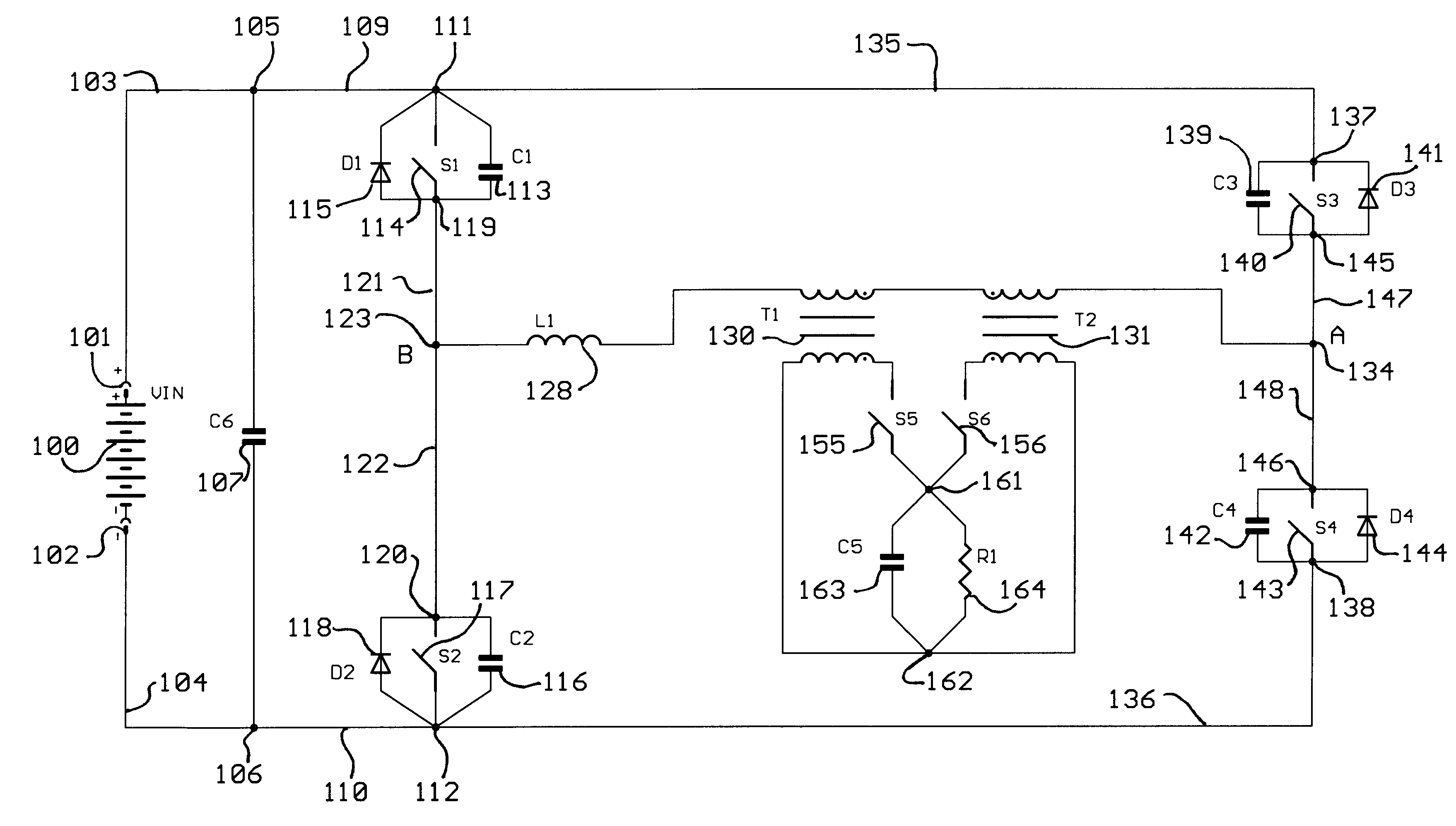
FIG. 22 illustrates an embodiment of the subject invention, in which the secondary switches are implemented using diodes and the primary switches are implemented using power mosfets. The power mosfets contain the switch, as a semiconductor field effect transistor switch, the diode as the intrinsic body drain diode of the power mosfet, and the capacitor as the mosfet output capacitance. The diode provides a natural turn off at the time that the current drops to zero, as needed.

FIG. 40 shows an embodiment related to the FIG. 22 embodiment in which a pair of diodes D3 and D4 are added to clamp potential ringing due to the interaction of L1 with the parasitic junction capacitances of D1 and D2.

The control block suggests that either phase shift modulation or pulse width modulation may be used. There is nothing that would prevent either control method from being employed in this invention. The phase shift modulation approach has been described here as an example of one control approach bu...


PUM


Abstract

The power converter of this invention accomplishes zero voltage switching at both turn on and turn off transitions of all primary switches. A pair of coupled inductors serve as both energy storage devices and isolation mechanisms. The placement of a small inductor in series with the coupled inductors enables the invariance of primary current direction throughout the switching transition which provides for zero voltage switching for all switches for all transitions. The power converter behaves as a pair of interleaved coupled inductor buck converters with oppositely directed magnetizing currents. During a first half cycle, while one inductor is coupled to the output, the other uncoupled inductor behaves as a current source, setting the primary winding currents for both inductors equal to the magnetizing current of the uncoupled inductor. The inductor which is coupled to the output appears as an output filter capacitor or voltage source to the uncoupled inductor during the first half cycle. During the alternate half cycle the roles of the two inductors are reversed.

Description

1. Field of the InventionThe subject invention generally pertains to electronic power conversion circuits, and more specifically to high frequency, switched mode power electronic converter circuits.2. Description of Related ArtThere are some power conversion circuits which accomplish higher efficiencies by implementing a mechanism that accomplishes switching at zero voltage. Power loss in a switch is the product of the voltage applied across the switch and the current flowing through the switch. In a switching power converter, when the switch is in the on state, the voltage across the switch is zero, so the power loss is zero. When the switch is in the off state, the power loss is zero, because the current through the switch is zero. During the transition from on to off, and vice versa, power losses can occur, if there is no mechanism to switch at zero voltage or zero current. During the switching transitions, energy losses will occur if there is simultaneously (1) non-zero voltage ...

Claims


Application Information

Patent Timeline
IPC IPC(8): H02M3/337H02M3/24H02M3/335
CPCH02M3/33592H02M3/3378Y02B70/1475Y02B70/10
Inventor WITTENBREDER, ERNEST H.
Owner TECHN WITTS
Why Eureka
Try Eureka