Differential thermopile heat flux transducer

a heat flux transducer and thermopile technology, applied in the field of differential thermopile heat flux transducers, can solve the problems of difficult or impossible to predict the installed performance of insulative materials in laboratory experiments, difficult or impossible to acquire accurate, useful data with heat flux sensors, etc., and achieve the effect of not being able to measure heat flux through a surface and a large area

Inactive Publication Date: 2001-08-21
VATELL CORP
View PDF4 Cites 143 Cited by
  • Summary
  • Abstract
  • Description
  • Claims
  • Application Information

AI Technical Summary

Problems solved by technology

However, it is often difficult to acquire accurate, useful data with heat flux sensors.
This is because it is often difficult or impossible to predict the installed performance of insulative materials from laboratory experiments.
The heat flux through a surface cannot, however, be measured without some disturbance caused by insertion of the measuring device into the path of heat flow.
However, when the series thermal resistance of a thermopile type heat flux transducer is very low, its sensitivity may also be low because the low thermal resistance only produces a small temperature difference.
This solution is not effective when the sensor has high thermal resistance, because the measured heat flux is that which passes through the sensor, and it is reduced by the sensor's thermal resistance.
Unless the areas of the sensor covering the wall studs and the surrounding structure are in the same proportion as in the entire structure, this practice introduces an error.
Another disadvantage of large area heat flux sensors is that they are relatively expensive.
The manufacturing method has certain drawbacks which limit the sensor performance and restrict the range of applications.
The manufacturing cost of the sensor is high because it is made by multiple stages of sputtering through shadow masks.
Another drawback is the relatively low sensitivity of the sensor.
Prior heat flux sensors also suffer additional drawbacks.
Prior heat flux sensors fail to be equally responsive in sensing radiation, convection and conduction heat transfer.
Moreover, such prior heat flux sensors are not responsive to heat transfer in both directions through the sensor.
In addition, such prior sensors cannot be bent over a radius without loss of continuity or calibration.

Method used


Image

  • Differential thermopile heat flux transducer
  • Differential thermopile heat flux transducer
  • Differential thermopile heat flux transducer

Examples


Embodiment Construction

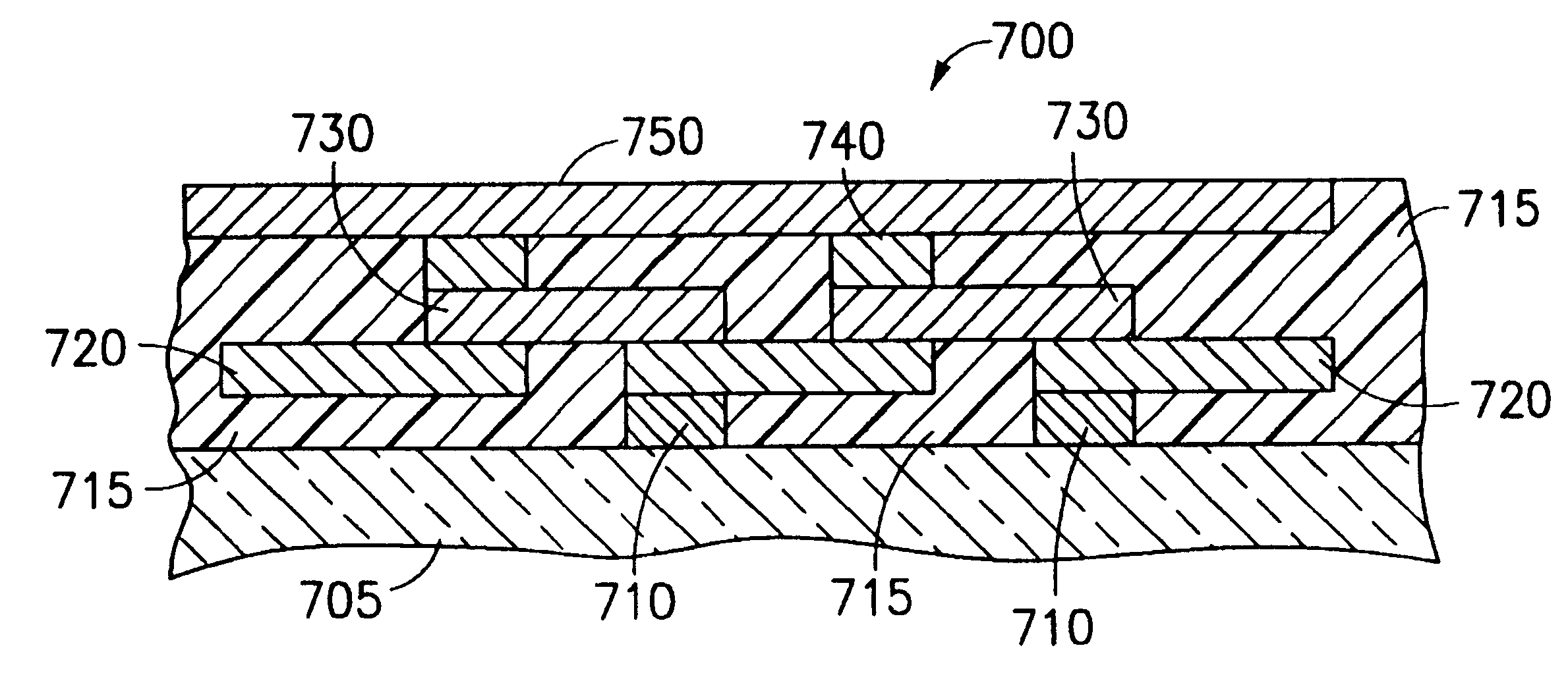
With reference to the attached drawings, the structure and development of the preferred embodiment (the "Episensor") of the present invention will now be described. Identical reference numerals in different drawings refer to the identical structure. The first number of each reference numeral indicates the first figure in which that reference numeral has been introduced.

Development of the Episensor

1. The 1st Generation Improved Heat Flux Sensor

In U.S. Pat. No. 5,990,412, herein incorporated by reference, a heat flux sensor and its method of manufacture, which contained various improvements over prior known heat flux sensors and their methods of manufacture, were disclosed. This first generation improved heat flux sensor is depicted in FIG. 1. With reference to FIG. 1, the sensor 100 consists of a thin sheet of aluminum 120 which has been anodized on at least one surface 130. Anodization produces a thin aluminum oxide layer 140 to electrically insulate the sensor elements from the alu...


PUM

PropertyMeasurementUnit
temperatureaaaaaaaaaa
thicknessaaaaaaaaaa

Abstract

A thin sensor for heat flux and temperature, designed for adhesive attachment to a surface, is manufactured on a flexible insulated metallic substrate. The sensor exhibits a combination of high sensitivity for heat flux and low resistance to the flow of heat. These characteristics enable it to measure heat flux at surface boundaries with improved accuracy over conventional heat flux transducers because the temperature drop produced by the sensor is very small. The response by the sensor to radiation, convection and conduction are equal. As such, the sensor can be calibrated in one mode of heat transfer and used for measurement in other modes. The high sensitivity of the sensor makes it ideal for measuring heat flow through insulating materials, and well adapted to instrumenting heat flow in buildings, detecting fires at an early stage, or remotely measuring the temperature of string and web products in industrial processing.

Description

1. Field of the InventionThe present invention is related generally to heat flux transducers and, more particularly, to a differential thermopile heat flux transducer having a plurality of layers and a high thermal conductivity top coating which enables the transducer to measure heat flux with improved accuracy.2. Description of the Related ArtHeat flux sensors are routinely used to measure the rate and direction of heat energy flow. For example, heat flux sensors (or "transducers") have been used in building energy management applications since the 1950's. Methods for using heat flux transducers to evaluate thermal performance of building materials are generally well understood. Heat flux transducers designed for surface mounting are inexpensive and easy to install. However, it is often difficult to acquire accurate, useful data with heat flux sensors.In combination with a temperature sensor disposed at the same location, a heat flux sensor and a temperature sensor can be used to m...

Claims


Application Information

Patent Timeline
Patent Type & Authority Patents(United States)
IPC IPC(8): G01K17/20G01K17/00H01L35/32H01L35/34H01L35/00
CPCG01K17/20H01L35/34H01L35/32H01L35/00H10N10/00H10N10/01H10N10/17
Inventor PEABODY, HUME L.
Owner VATELL CORP
Why Eureka
Try Eureka