Closed electron drift plasma thruster with a steerable thrust vector

a plasma thruster and electron drift technology, applied in plasma, electrical equipment, plasma technique, etc., can solve the problems of not using industrial embodiments using that type of technique, not using industrial embodiments, and not increasing etc., to achieve easy and effective control of the thrust vector, increase the cost or overall on-board mass, and the effect of increasing the cos

Inactive Publication Date: 2001-08-28
SN DETUDE & DE CONSTR DE MOTEURS DAVIATION S N E C M A
View PDF8 Cites 32 Cited by
  • Summary
  • Abstract
  • Description
  • Claims
  • Application Information

AI Technical Summary

Benefits of technology

The invention seeks to remedy the above-specified drawbacks, and in particular to steer the thrust vector by means of a system that does not excessively increase cost or overall on-board mass, and consequently does not comprise a full set of

Problems solved by technology

Since mechanisms for controlling the thrust vector are naturally rather complex, numerous attempts have been made to replace mechanical thrust control by control that is electrostatic or electromagnetic.
Nevertheless, no industrial embodiment has yet been implemented using that type of technique.
Nevertheless, that disposition has never been used on an operational thruster.
Although the various techniques for electro-magnetically controlling the thrust vector of a closed electron drift thruster make it possible to obtain deflection angles of up to 30, they present a series of drawbacks due specifically to the physics of such thrusters.
Insofar as it is necessary to change the reference direction in which the beam is pointed, the interface between the plasma and the worn channel wall is no longer symmetrical.
This gives rise to wear that is more marked on the side that was previously subjected to moderate wear, but in particular it gives rise to the wear threshold being disp

Method used


Image

  • Closed electron drift plasma thruster with a steerable thrust vector
  • Closed electron drift plasma thruster with a steerable thrust vector
  • Closed electron drift plasma thruster with a steerable thrust vector

Examples


Embodiment Construction

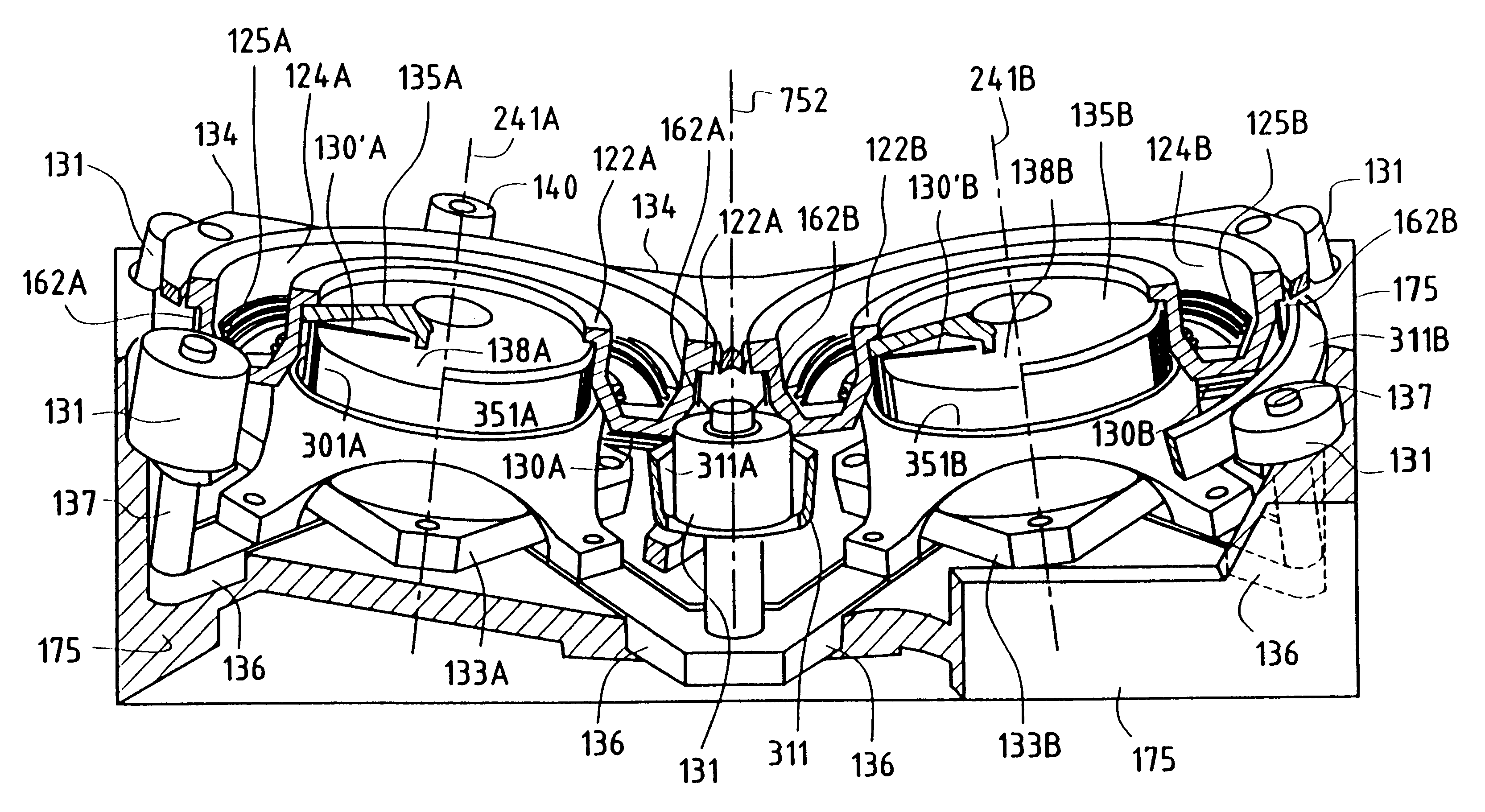
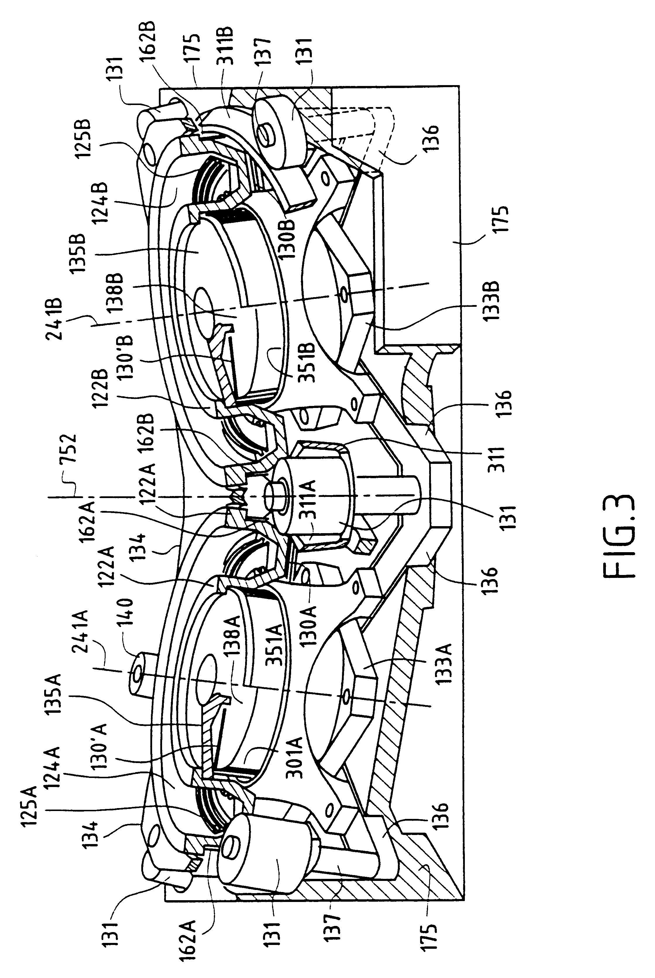
In the following description of various embodiments of closed electron drift plasma thrusters provided with respective pluralities of main annular ionization and acceleration channels, items that are similar in the various main annular channels or that are associated with the various different channels are given the same references, but followed by a letter A, B, C, or D depending on whether reference is being made to a first, a second, a third, or a fourth annular channel of a single thruster.

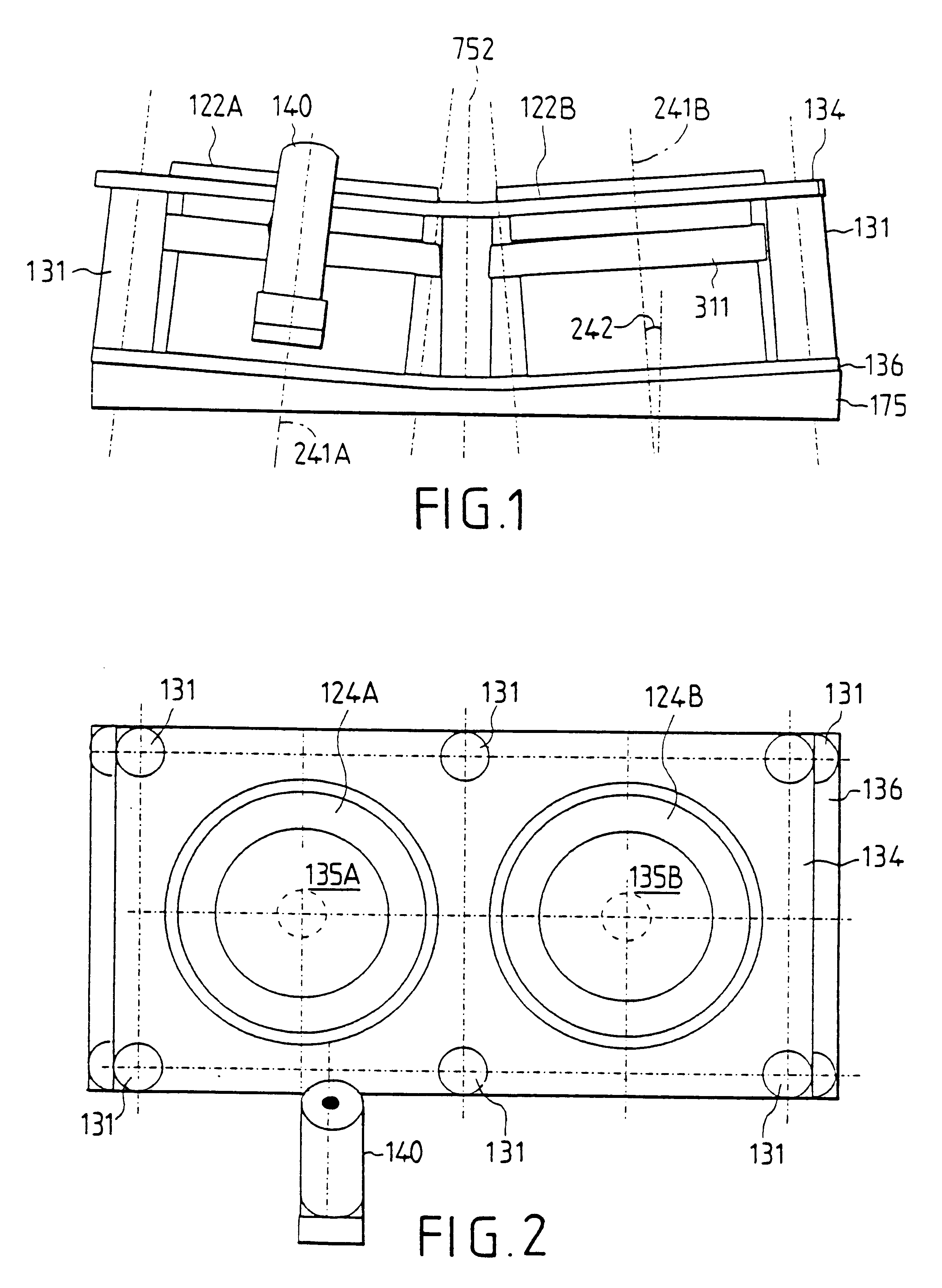
FIGS. 1 to 3 show a plasma thruster having two main annular channels 124A and 124B disposed side by side and defining a configuration that is essentially rectangular. The axes 241A and 241B of the two channels 124A and 124B are inclined at an angle 242 relative to the geometrical axis 752 of the thruster. A single hollow cathode 140 is associated with the two main channels 124A and 124B.

A conventional plasma thruster having a single main annular channel, of the kind shown in FIG. 16, includes,...


PUM


Abstract

The thruster comprises, on a common plate, a plurality of main annular ionization and acceleration channels having axes that are not parallel and that converge in the outlet direction of the channels. A magnetic circuit sets up a magnetic field in the annular channels. The thruster also has a hollow cathode, a device for regulating the ionizable gas feed rate to each annular channel, and a device for controlling the ion discharge acceleration current in the channels. The direction of the thrust vector of the thruster can be controlled without significantly increasing the mass of the thruster.

Description

The invention relates to a closed electron drift plasma thruster having a steerable thrust vector, the thruster comprising at least one main annular ionization and acceleration channel fitted with an anode and ionizable gas feed means, a magnetic circuit for creating a magnetic field in said main annular channel, and a hollow cathode associated with the ionizable gas feed means.PRIOR ARTBy steering the thrust vector of ion thrusters or of closed electron drift thrusters, it is possible to perform attitude control operations by offsetting the thrust vector from the center of gravity of the satellite, or on the contrary, it is possible to counteract parasitic torques by aligning the thrust vector in such a manner as to track the displacements of the center of gravity of the satellite as induced by thermal deformation and by consumption of propellant.This need has been recognized since the 1970s. Since mechanisms for controlling the thrust vector are naturally rather complex, numerous ...

Claims


Application Information

Patent Timeline
IPC IPC(8): F03H1/00
CPCF03H1/0075
Inventor VALENTIAN, DOMINIQUEKLINGER, ERICLYSZYK, MICHEL
Owner SN DETUDE & DE CONSTR DE MOTEURS DAVIATION S N E C M A
Why Eureka
Try Eureka