Tunable add/drop optical device

a technology of optical switches and optical switches, applied in the direction of electromagnetic repeaters, transmission monitoring, instruments, etc., can solve the problems of limiting the total number of cells, imposing cost and power loss considerations, and requiring two optical switch arrays that are relatively burdensome and costly, so as to reduce complexity and cost

Inactive Publication Date: 2001-09-04
STMICROELECTRONICS SRL
View PDF3 Cites 88 Cited by
  • Summary
  • Abstract
  • Description
  • Claims
  • Application Information

AI Technical Summary

Benefits of technology

One objects of the present invention is to implement a tunable add / drop device free of the drawbacks and limitations mentioned above with reference to the prior art devices. A particular object is that of implementing a device having a reduced complexity and cost as compared to the known devices.

Problems solved by technology

In principle, known multiplexing and demultiplexing optical filters have an architecture that permits optimization adjustments of their performance (trimming) in terms of selectivity and of power losses, but their configuration remains substantially unmodifiable.
On the other hand, it is evident that cost and power loss considerations impose to limit the total number of cells, that is of phase shift stages, employed for implementing the filter.
With present state-of-the-art, optical switches must be implemented by the use of mechanical devices and therefore the two necessary arrays of optical switches are relatively burdensome and costly.
Moreover, each of the two required WGR devices may also be regarded as a WDM array and therefore overall system complexity is not negligible.

Method used


Image

  • Tunable add/drop optical device
  • Tunable add/drop optical device
  • Tunable add/drop optical device

Examples


first embodiment

based on the exploitation of a thermo-optical effect, only a heating strip is used. According to a different embodiment, a Peltier cell is applied on the opposite face of the device juxtaposedly each heating strip. According to this alternative embodiment, the performance in terms of a more effective thermal dissipation and tuning times of the device is improved.

By employing a Peltier cell (not illustrated in the figures) on the face of the device opposite to the one on which the heater is disposed, it is possible to confine more precisely the heated zone in the vicinity of the portion of waveguide to be heated, by ensuring a "local" heat dissipation to prevent undesired propagation from the heater toward other portions of waveguide that should not be heated.

By recalling the fact that the tuning is based on the introduction of an offsetting delay on only one of the two optical paths that form the phase-shift stage, the heating must involve only one of the two optical waveguides.

The ...

example 1

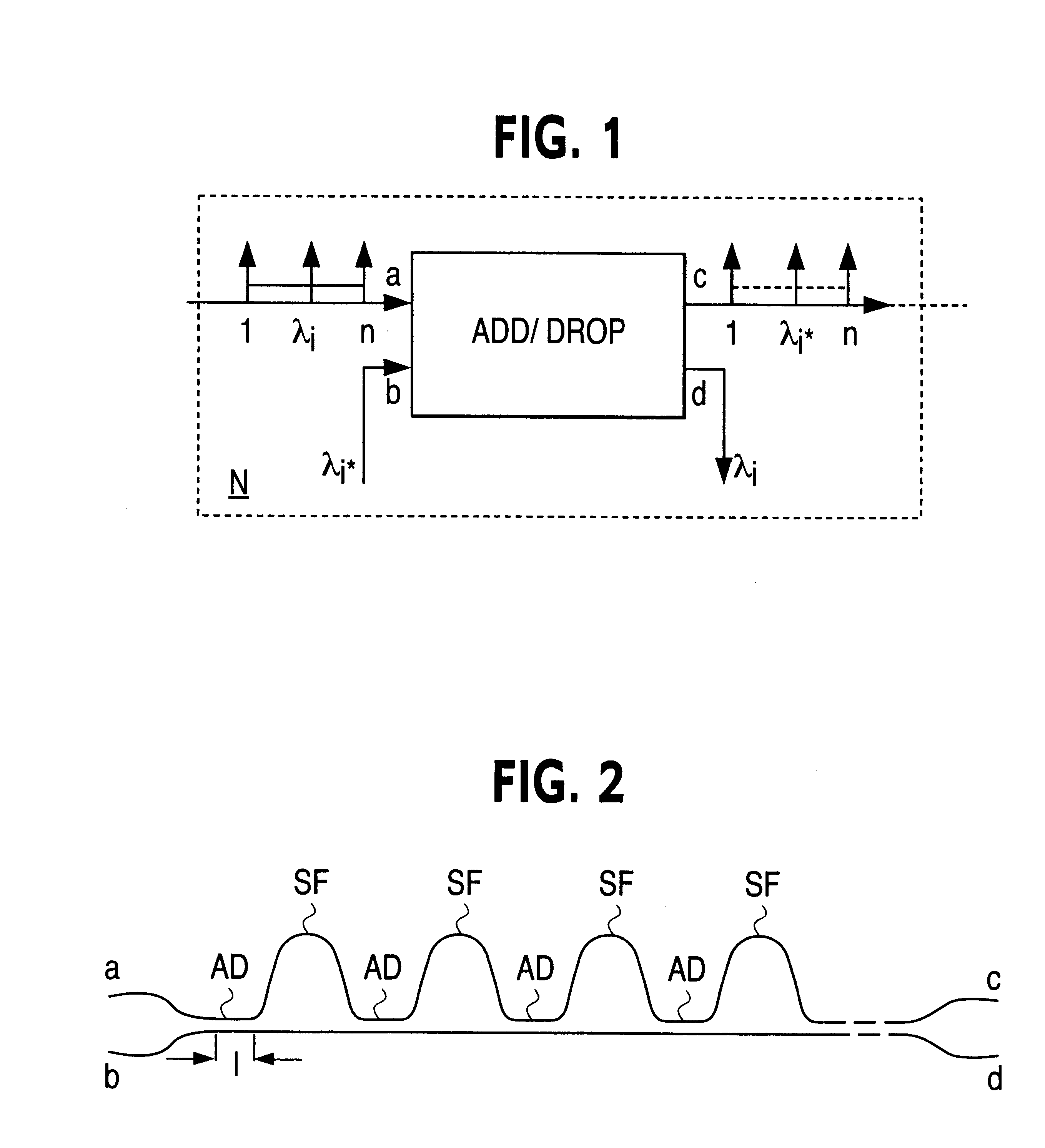
A tunable "1-from-4" addidrop filter based on the principle of a resonating optical coupler has been realized in accordance with the present invention. The functional diagram of the device is schematically reproduced in FIG. 11, while each single cell of the interferometers device is depicted in FIG. 12.

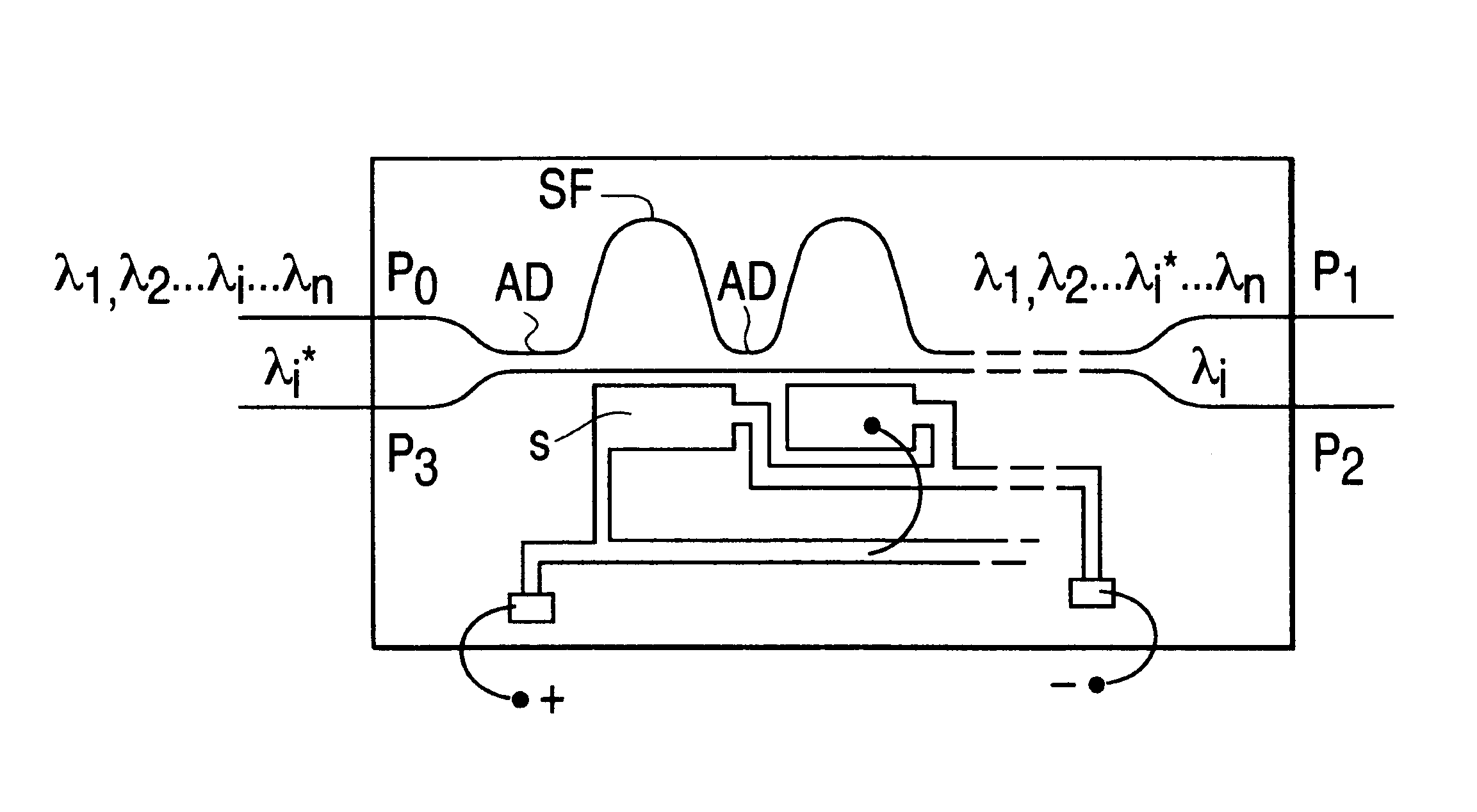
One of the four wavelengths managed by the tunable device, present on the through input P1 port is directed to the drop output (Cross P4 port), while the other three wavelengths are directed to the through output port (Bar P2 port). Simultaneously, a local transmitter introduces a channel on a second input port (Bar P3 port) having the same carrier wavelength of the channel that is directed toward the drop output port (Cross P4 port), directing it to the second through output port (Cross P2 port).

An overall layout of the device is depicted in FIG. 13.

The device has been realized in a socalled "Glass-on-Silicon" technology with a lower cladding layer of phosphorus doped SiO.sub.2 havi...

example 2

A second prototype filter has been realized by using the same fabrication techniques and the same technological parameters used in the Example 1, but inverting the relative dimensioning of the first two Mach-Zehnder interferometers so as to correspond to the following architecture parameters: ##EQU8##

The response characteristics of this second prototype are substantially superimposable in terms of FWHM to those of the prototype of Example 1, thus demonstrating the possibility of obtaining the same FWHM with a different position of the MZI stage of different phase shift, which need to be such as to optimize the FWHM / FSR ratio and the secondary lobes (or sidelobes) level in a strict correlation between each other.

According to an important further aspect of the invention, several tunable devices may be interconnected in a loop arrangement to implement add / drop functions for an incremented number of channels or carrier wavelength, without substantially incrementing the insertion losses ...


PUM

PropertyMeasurementUnit
FWHMaaaaaaaaaa
FWHMaaaaaaaaaa
thicknessaaaaaaaaaa

Abstract

Tunable add/drop optical device for injecting or extracting (add/drop) at least a selected optical channel or carrier wavelength in or from a set of multiplexed channels or carriers of different wavelengths comprising a plurality of directional couplers (AD1 . . . AD6) and a plurality of phase-shift stages (SF1 . . . SF5) alternately connected in cascade, wherein each phase-shift stage defines a certain optical path length difference (DELTAL1 . . . DELTAL5) between two distinct optical paths of the stage. The tuning is performed modifying the refraction index of one path of said phase shift stages by means of Joule effect heating strips (L1 . . . L5) or by means of metallic field plates adapted to receive a signal suitable to modify the electric field intensity. The first two phase-shift stages of said plurality of phase-shift stages have differences of length of optical paths different from each other and in a preestablished ratio while the remaining phase-shift stages have differences of length of optical paths identical. It is thus possible to provide a device having an exceptionally flat cross response characteristic, substantially free of ripple due to an inevitable truncation of the Fourier expansion series.

Description

The present invention relates to optical telecommunication systems functioning in a wavelength division multiplexing (WVDM) mode. More in particular the invention concerns a passive four port optical coupling device for wavelength division multiplexed optical signals which may be used as a filter for injecting or extracting (add / drop) an optical carrier signal or channel of a selected wavelength, from a plurality of WDM channels of distinct wavelengths.In the transmission of information through an optical fiber network, the wavelength division multiplexing (WDM) technique is employed for incrementing the efficiency of the network system. WDM signals consist of a plurality of optical signals of different wavelength, referred to as carriers or channels through which information may be transmitted on a fiber.FIG. 1 shows a node N of an optical fiber transmission network that includes an add / drop device to an input port or gate to which a fiber may be coupled, carrying n optical channel...

Claims


Application Information

Patent Timeline
Patent Type & Authority Patents(United States)
IPC IPC(8): G02F1/313G02F1/29G02F1/01H04B10/2507H04B10/29H04B10/40H04B10/43H04B10/50H04B10/548H04B10/60
CPCG02F1/3136G02F1/0147
Inventor FINCATO, ANTONIOLENZI, MAURIZIODI MOLA, DOMENICO
Owner STMICROELECTRONICS SRL
Why Eureka
Try Eureka