Image modifiers for use in photography

a technology for modifiers and images, applied in the field of photographic image modification equipment, can solve the problems of uncontrolled light from a particular region of the framed scene reaching the corresponding region of the film without affecting the amount of light reaching the other regions of the film

Inactive Publication Date: 2001-09-04
SMARTLENS CORP
View PDF19 Cites 33 Cited by
  • Summary
  • Abstract
  • Description
  • Claims
  • Application Information

AI Technical Summary

Benefits of technology

to provide optically-generated grain effects to film without adversely effecting other characteristics of the film.
It is another object of the invention to provide such a device which enables a photographer to transform photographic images into images having characteristics inherent in paintings of such images.
It is another object of the invention to provide such a device which enables a photographer to superimpose a translucent mask including random crackling onto an image, resulting in a final print which includes the craquelure characteristics of aged oil paintings.
It is another object of the invention to provide such a device which enables a photographer to superimpose a translucent mask onto an image to transpose the image to one having characteristics inherent in a water color painting.
It is yet another object of the invention to provide movement of a selected modifier during exposure so that a multitude of effects can be generated from a single modifier.
In yet another embodiment of the invention, a disposable SLR-type camera includes a pivotal mirror located between the camera's lens and eyepiece that may be rotated to a first position wherein incoming light from an image is directed to the eyepiece, and a second position wherein the incoming light is directed to film. The rotatable mirror may function as a light modifier and may be easily replaced with other modifiers.

Problems solved by technology

Typically, these devices are attached at the end of the lens of a camera, and directly interfere with the light prior to it reaching the film.
This results in an unexposed area of film which may be later "filled-in" with another image to create one desired illusion or effect.
One limitation with these prior art special effects devices is that they all rely on blocking a portion of the incoming light prior to the light reaching the film.
Although the use of several light meters to measure the different light intensities at different regions of a framed scene provides a more accurate average light intensity reading, the camera cannot control the amount of light from a particular region of the framed scene reaching the corresponding region of the film without effecting the amount of light reaching the other regions of the film.
If the speed of the shutter is prolonged to "burn in" the darker regions of the image, the normal areas will become unacceptably overexposed and appear "washed out".
Unfortunately, since a conventional camera merely measures the average of the total received light entering the camera of a particular image, many pictures end up with a portion of the recorded image either overexposed (to dark) or underexposed (washed out).
There are several problems with the bracketing technique of photography.
Not only is a lot of film exposed for few different images, only relatively expensive cameras offer exposure control, let alone automatic bracketing of the exposure.
Also, although exposure bracketing provides several pictures to select from, since the camera's exposure meter must account for the total received light and may not locally correct the exposure of a portion of the image frame, all of the bracketed pictures will show varying degrees of over and under-exposure.
In other words, if there is an overexposed region of an image, bracketing will not correct the exposure of that particular region, merely hide it by changing the total exposure throughout the image, as recorded by film.
These filters rarely align with the image detail and are only useful when the specific regions defined by the filter align with the regions of the scene.
However, these techniques are used in expensive custom print processing, not in cheaper automated print processing.
These techniques are difficult to uniformly perform on a repeated basis because of the inherent inaccuracies in placing the density mask in the proper location each time a print is made and also require a great amount of time to adjust the mask from print to print.
Furthermore, the results of these exposure compensating techniques are not known until after the print is exposed and developed.
If the results are unsatisfactory, another attempt must be made in a trial-and-error method until a satisfactory print is produced.
High speed films, such as 1600 ISO have a tendency to record an image with high grain characteristics, resulting in a somewhat blurred image revealing "soft" detail.
Since emulsion grain tends to "dull" an image by lowering the recorded resolution of the film, this film characteristic is generally considered undesirable and much research and development has been directed to eliminating (or at least minimizing) the effects of grain from any processed photograph, either at the transparency or negative stage, or in the final print.
Graininess is also generally undesirable by photographers because by achieving high grain in a negative, the tonal depth of the image is adversely effected, as described above.
This digitizing of the tonal information of the image tends to create a dull, choppy, high-contrast, recorded image having little tonal depth or realism.
Also, this process of using potato starch to introduce a grain-like characteristic to a photographic print is considered custom photographic work and is inherently expensive to implement, by only select professional photographic labs.

Method used


Image

  • Image modifiers for use in photography
  • Image modifiers for use in photography
  • Image modifiers for use in photography

Examples


Embodiment Construction

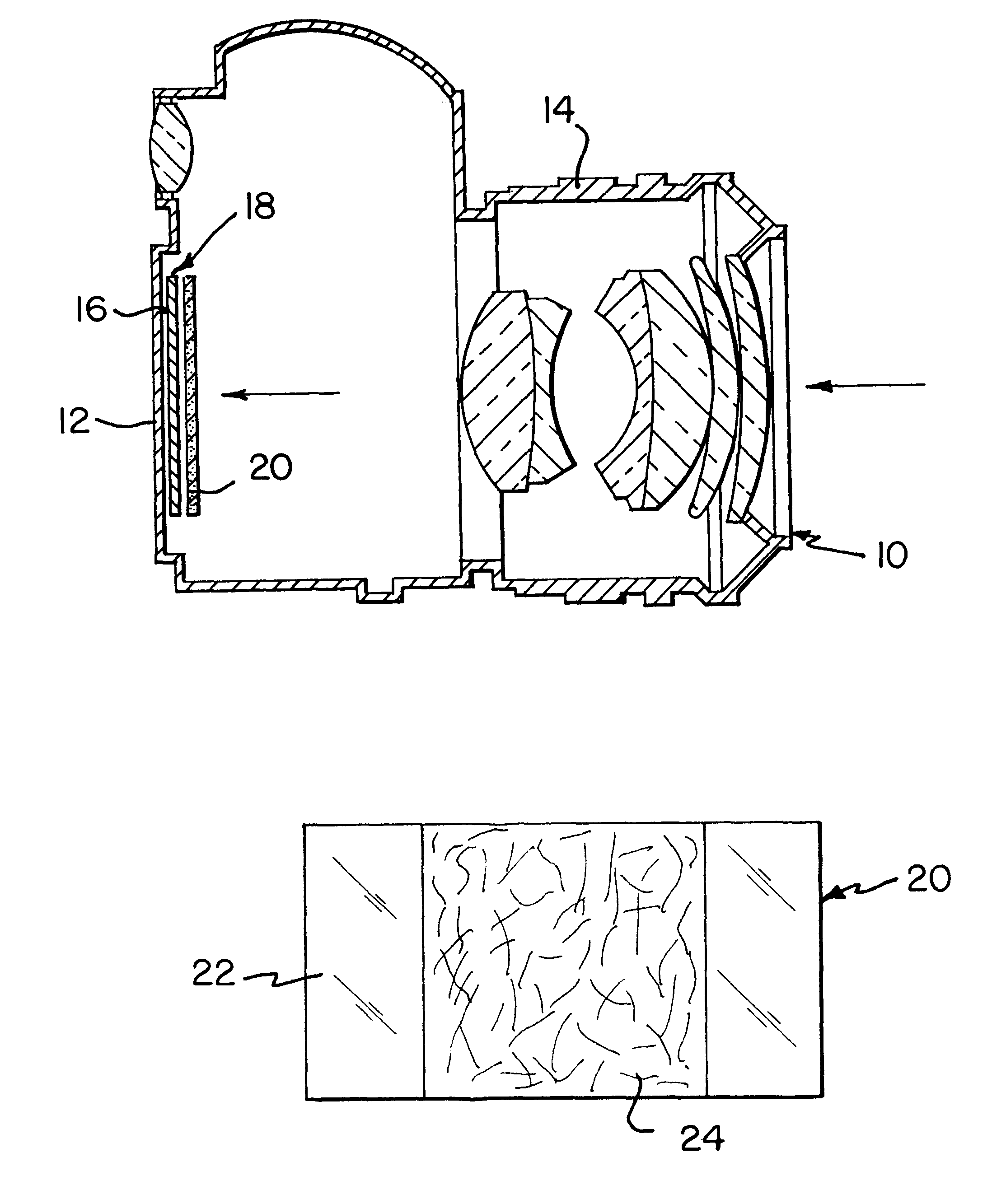
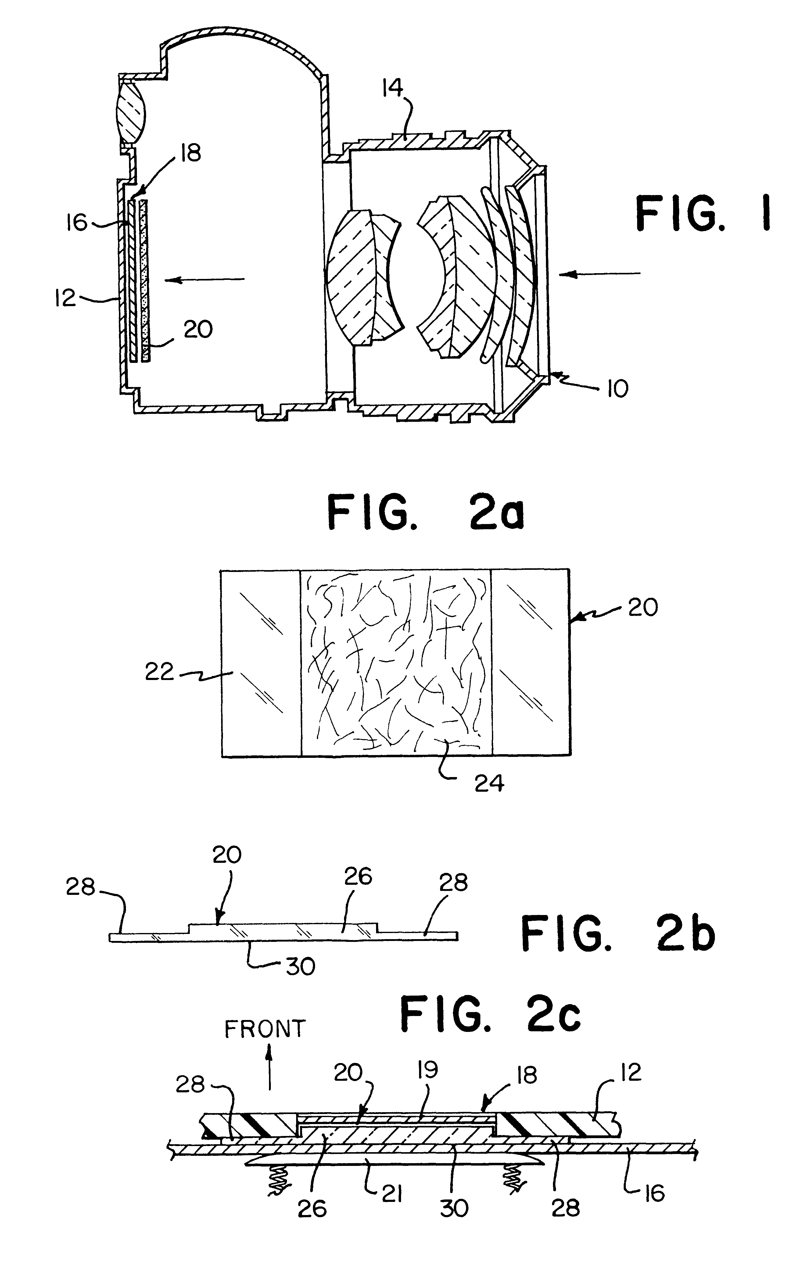
Referring to FIG. 1, a camera 10 (an SLR) is shown having a camera body 12, a lens assembly 14 attached to a front side of the camera body 12, and a frame of film 16 shown in cross section at a film gate 18 (see also, FIG. 2c). An optical modifier 20, in accordance with a first embodiment of the invention, is positioned in front of the film 16 within the film gate 18. The specific structures of both the film gate 18 and the shutter mechanism 19 of the camera 10 are conventional and are therefore not shown in full detail. In this embodiment, the shutter mechanism 19 is located in front of (i.e., closer to) the lens 14, the modifier 20 and, of course, the frame of film 16.

The modifier 20, described in greater detail below, is sized and shaped to fit within the film gate 18 between the film 16 and the shutter of the camera 10. A conventional, spring-loaded, film pusher plate 21 which is usually mounted to the inside surface of the door (not shown) of the camera (used to access the film...


PUM


Abstract

In a first embodiment of the invention, a transparent plate is mounted at the film plane within a camera. The transparent plate includes a translucent diffusion pattern which diffuses incoming light rays reflected from the subject and effectively repositions them in a controlled manner prior to the light exposing the film. Proposed diffusion patterns may alter the light rays to create characteristics indicative of various types of paintings or may produce a controlled grainy appearance to an image recorded on film.In another embodiment of the invention, the transparent plate is mounted in a film cartridge.In another embodiment of the invention, a length of plastic film (a pattern strip) is positioned adjacent to a similar length of photographic film (film strip). An appropriate translucent diffusion pattern is provided onto one surface of the pattern strip, along its entire length. Both strips are rolled into a conventional 35 mm film canister and dispensed simultaneously, as needed (within the camera) so that each frame of film has a separate mask in front of it, at the film gate of the camera.In another embodiment of the invention, a transparent plate having a translucent diffusion pattern is positioned between the main lens of the camera, and the camera body. In this arrangement, a correcting lens is required to bring the pattern of the particular pattern into sharp focus with the image at the film plane to be exposed on film.

Description

a) Field of the InventionThis invention relates generally to photographic image-modifying equipment, and more particularly, to photographic image-modifiers for introducing optically generated grain-effects to a photographic negative during its exposure of an image.b) Description of Related ArtThe art of creating special effects in the field of photography has been very active in the past and continues to grow with the increasing interest in photography and the desire for more interesting visual illusions. Devices have been developed, for example, to alter an image prior to or during its exposure on film. Typically, these devices are attached at the end of the lens of a camera, and directly interfere with the light prior to it reaching the film. The alterations of effects applied to the incoming light vary from common color-filtering changes to superimposing "sub-images" onto the same frame of film that is recording the "real" image. For example placing an opaque, pre-shaped matte in...

Claims


Application Information

Patent Timeline
Patent Type & Authority Patents(United States)
IPC IPC(8): G03B1/48G03B17/24G03B17/12G03B11/00G03B1/00
CPCG03B1/48G03B11/00G03B17/24G03B17/12G03B2217/26G03B2217/248
Inventor HYLEN, STEVEN H. L.
Owner SMARTLENS CORP
Why Eureka
Try Eureka