
Computer interface system for a robotic system

a robotic system and computer technology, applied in the field of interactive computer-based interface systems, can solve the problems of constant complicated and esoteric monitoring and control by the operator, the operation of the numerically controlled (nc) robotic system or the operation of the difficulty and complexity of the process of robotic system or machine tool operation, so as to eliminate erroneous human settings and facilitate the automatic operation and monitoring of the robotic system or the nc machine tool

Inactive Publication Date: 2001-09-18
NORTHROP GRUMMAN SYST CORP
View PDF15 Cites 131 Cited by
  • Summary
  • Abstract
  • Description
  • Claims
  • Application Information

AI Technical Summary

Benefits of technology

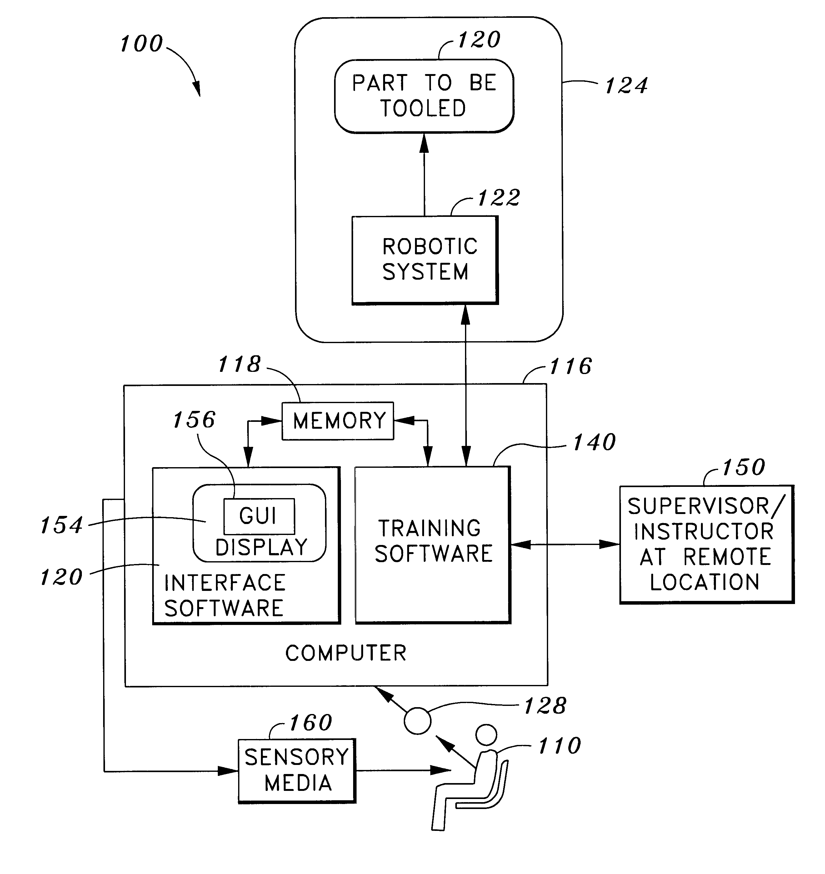
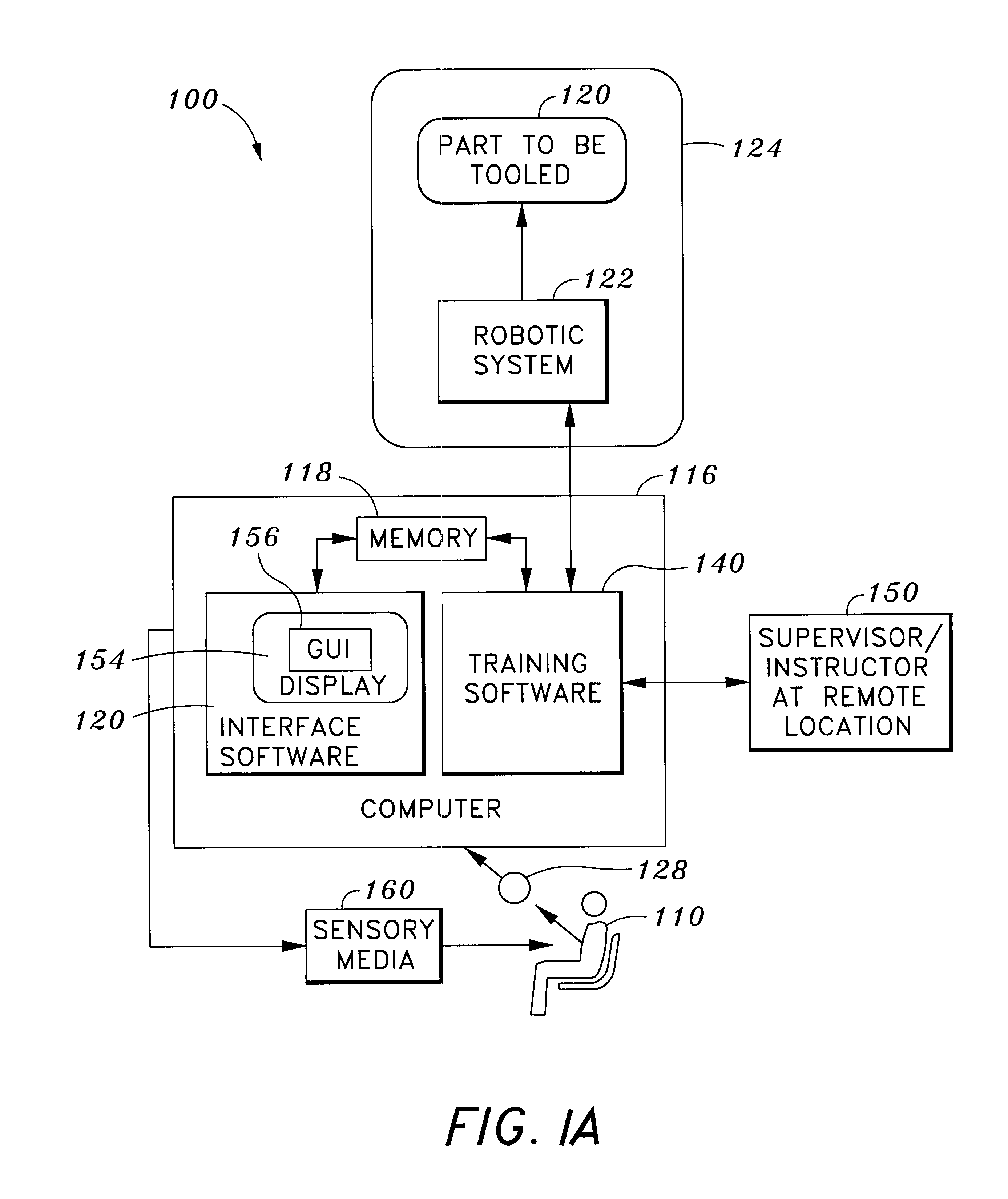
A feature of the present invention is the interactive software modules that allows real time operation and control of the outside devices. Another feature of the present invention is the easy to use and friendly graphical user interfaces and controls. Yet another feature of the present invention is the interface system that is preprogrammable for reducing the amount of custom and configuration settings that a tool operator must perform. An advantage of the present invention is that the interface system allows a person, such as a tool operator, to easily operate and monitor a robotic system or an NC machine tool automatically. Another advantage of the present invention is that the interface system controls part and tool settings, thereby eliminating erroneous human settings.
is that the interface system allows a person, such as a tool operator, to easily operate and monitor a robotic system or an NC machine tool automatically. Another advantage of the present invention is that the interface system controls part and tool settings, thereby eliminating erroneous human settings.

Problems solved by technology

Operation of a numerically controlled (NC) robotic system or machine tool can be a difficult and complex process.
Also, operation of the NC machine tool, after initial settings are configured, requires constant complicated and esoteric monitoring and control by the operator.
Consequently, not every machine tool operator can operate an NC machine tool.
This is an expensive and time consuming process.
Next, even if a specially trained NC machine tool operator is used to operate and control an NC machine tool, the element of human error is still present.
Even the best NC machine tool operator can make improper tool and part settings due to the complexity of the NC machine tool.
(Such errors may include, for example, the trainee selecting such a high velocity of a drill bit through a workpiece that the drill bit or workpiece would be overheated in a real machine operation.)

Method used


Image

  • Computer interface system for a robotic system
  • Computer interface system for a robotic system
  • Computer interface system for a robotic system

Examples


Embodiment Construction

Overview of Components

FIG. 3 is an architectural block diagram of a working example of the interface system of the present invention. In the following working example, the present invention is implemented in a gantry robotic device, such as the gantry device described in co-pending U.S. patent application Ser. No. 08 / 540,525 filed on Jun. 25, 1997, by the present inventor, Bullen, entitled NUMERICAL CONTROL MACHINE TOOL POSITIONING SYSTEM, with an interface system for assembling a vertical stabilizer. The gantry robotic device with an interface system 300 includes four main components, an assembly jig 302, a vertical stabilizer assembly 304, a gantry device 306, and a control station 308. The assembly jig 302 is a jig for holding a part, such as the vertical stabilizer assembly 304. The vertical stabilizer assembly 304 is a part that comprises subassembly components, including a frame 310, a skin 312, and fasteners 314. These subassembly components are to be assembled by the gantry ...


PUM


Abstract

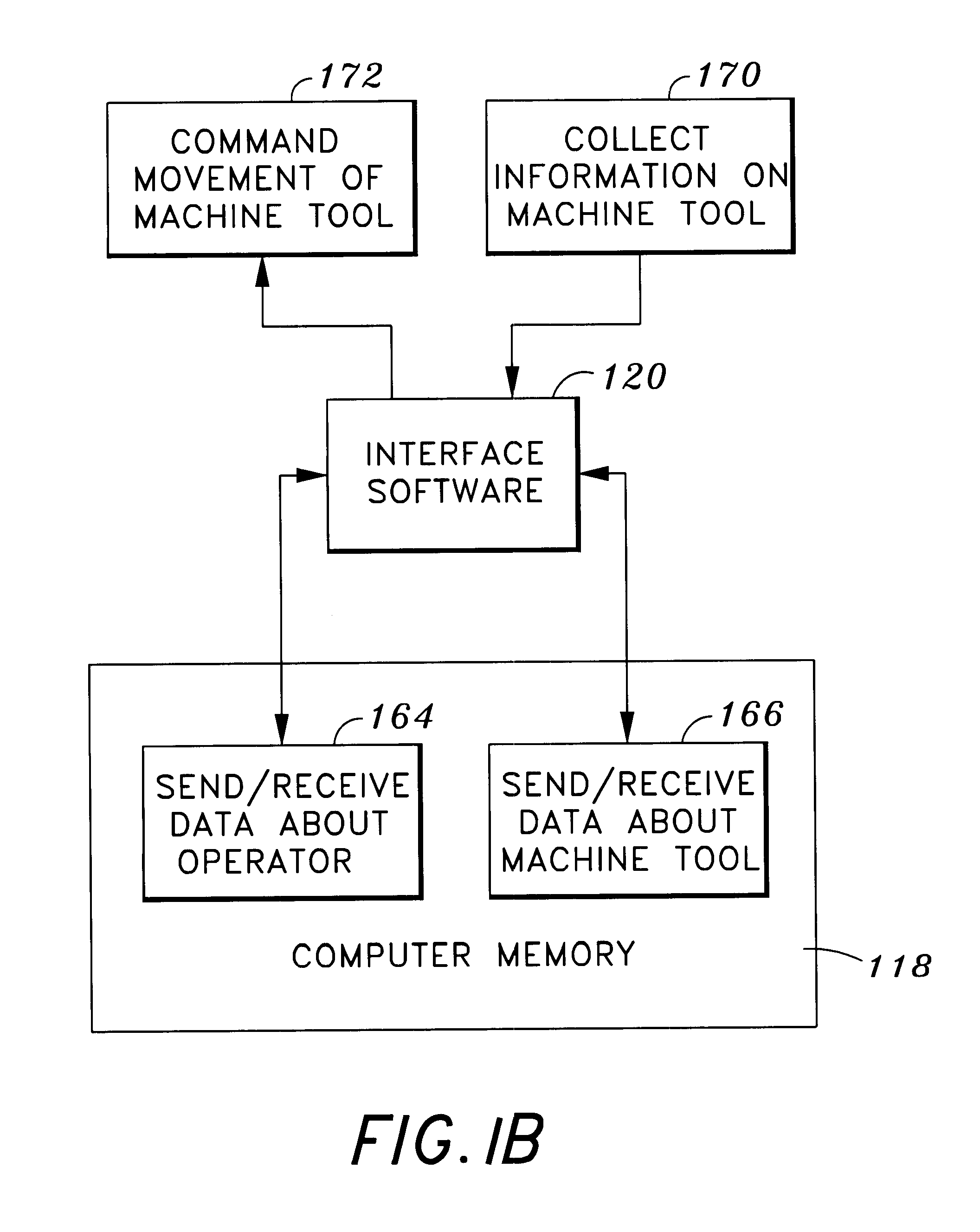
The present invention is an interactive multi-media interface system which incorporates text, audio, and video graphics animation and other tools to interface a user with a device in an outside environment, such as a robotic device, machining or other tool. The interface system includes a computer workstation to allow inputs from a user, such as a machine operator, computer memory, and an interface computer program operating on the computer. The computer has a graphical user interface for interfacing the operator with the workstation and to allow interactive operation and control of the machine tool. The operator can provide inputs to the interface system by various input devices such as a keyboard, cursor, mouse, a stylus pointing device or a touch sensitive screen. The interface software shares access to and exchanges data with the computer memory.

Description

1. Field of the InventionThis invention relates to interactive computer-based interface systems. More particularly, this invention relates to multi-media application software operating on a computer comprised of text, audio, video and computer graphics animation for interfacing an operator with an operable device, such as a robotic device, machining tool or other automatic tool in an environment outside the computer.2. Related ArtOperation of a numerically controlled (NC) robotic system or machine tool can be a difficult and complex process. NC machine tools must be preprogrammed with custom settings and configurations that are specific to certain parts before the tool can perform any tooling operations. Also, operation of the NC machine tool, after initial settings are configured, requires constant complicated and esoteric monitoring and control by the operator. Consequently, not every machine tool operator can operate an NC machine tool. Instead, usually only tool operators with s...

Claims


Application Information

Patent Timeline
Patent Type & Authority Patents(United States)
IPC IPC(8): G05B19/409
CPCG05B19/409G05B2219/35515G05B2219/35513G05B2219/35481
Inventor BULLEN, GEORGE NICHOLAS
Owner NORTHROP GRUMMAN SYST CORP
Learn More