Device for harmonizing a laser emission path with a passive observation path

a laser emission path and laser emission technology, applied in the direction of instruments, angle measurements, weapons, etc., can solve the problems of inability to harmonize the paths, local destruction of the films, and bulky housing

Inactive Publication Date: 2001-10-23
THOMSON CSF SA
View PDF87 Cites 31 Cited by
  • Summary
  • Abstract
  • Description
  • Claims
  • Application Information

AI Technical Summary

Problems solved by technology

If the emission wavelength of the laser is not included in the spectral band of the sensor of the imaging path or if the laser should send pulses that are too short to be detected by the sensor, it is not possible to harmonize the paths by taking a fraction of the laser beam and reflecting it to the sensor in order to determine the offset between the spot formed by the laser on the sensor and the center of the sensor.
In order to be visible in the band II or III, the heating must be substantial and lead to the local destruction of the film.
The housing is bulky and the solution described does not enable the harmonizing to be done during the operations of designation.
Nor does it permit the harmonizing to be done for operational lines of sight, especially when the system provides for a possible deflection of the line of sight.

Method used


Image

  • Device for harmonizing a laser emission path with a passive observation path
  • Device for harmonizing a laser emission path with a passive observation path
  • Device for harmonizing a laser emission path with a passive observation path

Examples


Embodiment Construction

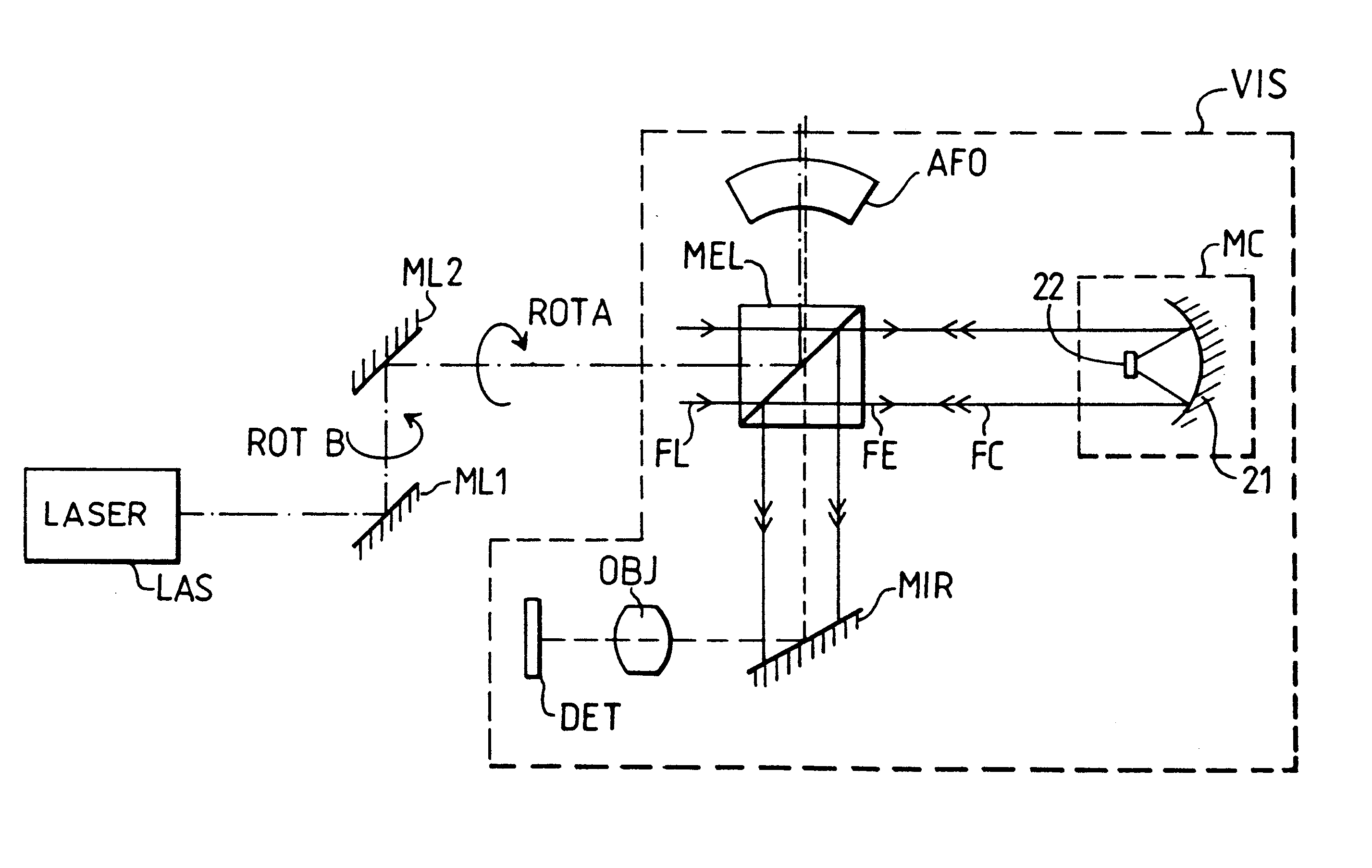
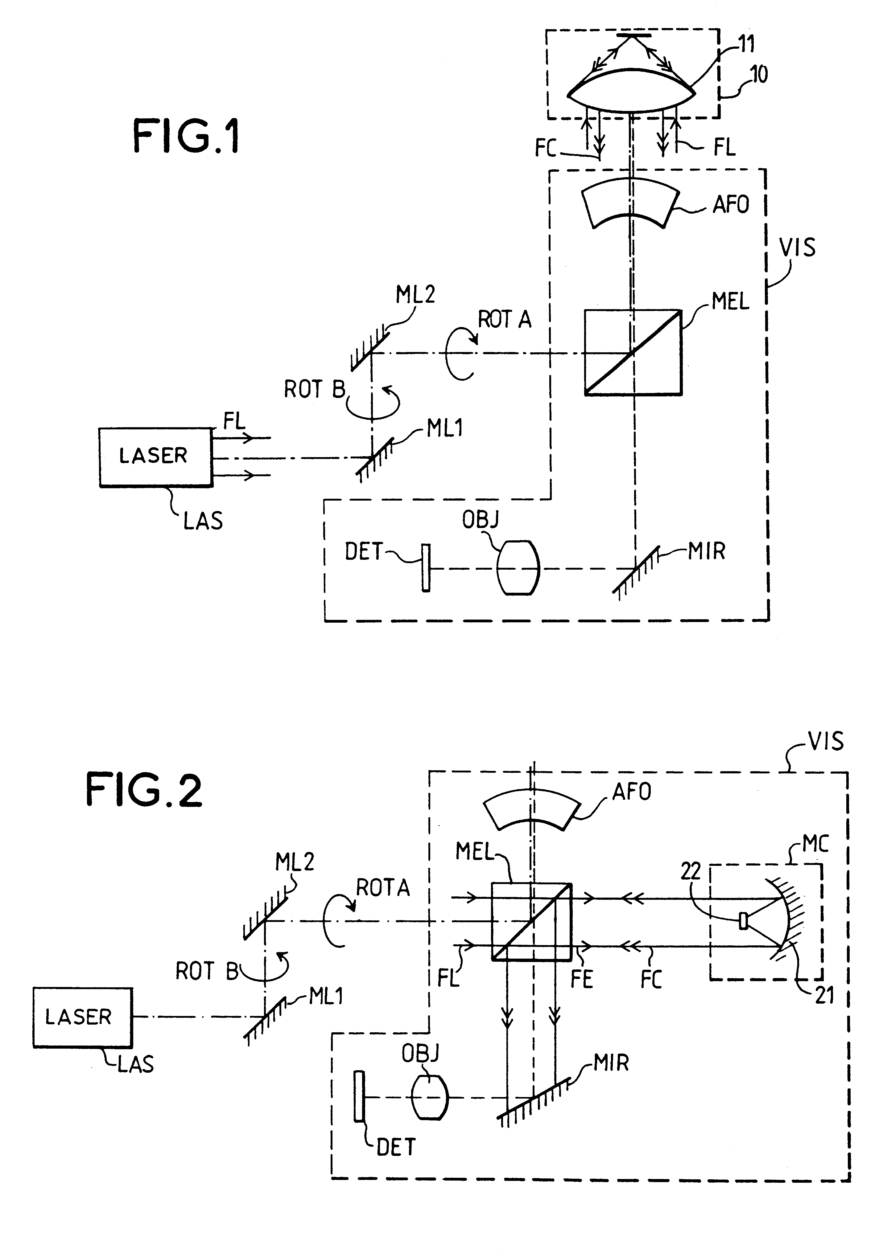
FIG. 1 shows a layout diagram of a harmonizing device according to the prior art described in the patent referred to here above in a pod type system of target designation by laser guidance. The system considered here has a emission path comprising a laser LAS emitting a laser beam FL whose optical axis is represented by dots and dashes in FIG. 1. The laser LAS is for example a Nd:YAG type pulsed laser emitting pulses of some tens of nanoseconds at 1.60 .mu.m for the designation functions and / or telemetry functions. In this example, the laser beam FL is substantially collimated. The system also has a passive observation path whose optical axis is shown in dashes in FIG. 1. This passive observation path comprises an objective OBJ and a detector DET, sensitive for example in the infrared, in the 3-5 .mu.m band or 8-12 .mu.m band. The detector may be an imager of the heat camera type or it may be an offset measurement device for example in the case of the designation of a target illumin...


PUM


Abstract

A device for harmonizing a laser beam path with an observation path for a target includes a laser that generates a laser beam; a first optical element that directs a first part of the laser beam toward the target along the laser beam path while directing a second part of the laser beam toward a conversion device; and a second optical element that directs a converted beam from the conversion device to a sensor that receives the converted beam and an image from the target. The conversion device includes a photoluminescent material that converts the second part of the laser beam into a converted radiation having a wavelength within a spectral band of the sensor, and an optical assembly that focuses the second part of the laser beam into the photoluminescent material and that collects at least a portion of the converted radiation to form the converted beam. The photoluminescent material can include photoluminescent ions such as erbium ions, or a semiconductor material such as indium arsenide. The photoluminescent material can include two materials, wherein the first material has a photoluminescence lifetime greater than a pulse duration of the pulsed laser beam, and the second material has an emission spectrum of photoluminescence covering at least a portion of a sensitivity spectral band of the sensor. The conversion device can also include a non-linear material that frequency converts the second part of the laser beam into an intermediary radiation having a wavelength shorter than the laser beam, and where the photoluminescent material converts the intermediary radiation into the converted radiation.

Description

1. Field of the InventionThe invention relates to a device for harmonization between a laser emission path and a passive observation path, the optical paths having axes that may be separate or the same. The harmonizing consists in making the optical axes of these paths parallel so that they have a common line of sight. The invention can be applied especially to target designation systems comprising a laser path and a passive observation path or the imager or offset measurement device type. It can be applied also to active / passive imaging systems comprising a scanning laser emission path and a passive imaging path. More generally, it can be applied to any system where the laser emission path and the passive observation path have to be harmonized.2. Description of the Prior ArtIn harsh environmental conditions, especially in terms of temperature and vibration, target designation by laser is advantageously done by means of a <<pod >> arranged for external carriage in the ai...

Claims


Application Information

Patent Timeline
Patent Type & Authority Patents(United States)
IPC IPC(8): F41G3/00F41G3/32
CPCF41G3/326
Inventor PAPUCHON, MICHELRABAULT, DENISDEFOUR, MARTINPOCHOLLE, JEAN-PAUL
Owner THOMSON CSF SA
Why Eureka
Try Eureka