Electromagnet, particularly a proportional magnet for operating a hydraulic valve

a proportional magnet and hydraulic valve technology, applied in the field of electromagnets, can solve the problems of unreasonably high total manufacturing cost of adjusting magnets of this type, unreasonably complex assembly, and the inability to achieve the desired effect, and achieve the effect of simple and inexpensive configuration

Inactive Publication Date: 2001-11-06
INA WALZLAGER SCHAEFFLER KG
View PDF10 Cites 62 Cited by
  • Summary
  • Abstract
  • Description
  • Claims
  • Application Information

AI Technical Summary

Benefits of technology

It is therefore an object of the invention to provide an electromagnet, particularly a proportional magnet for operating a hydraulic valve whose armature is provided with a

Problems solved by technology

A drawback of this prior art adjusting magnet is that, although the axial ball bearings for the rotary, longitudinal axial guidance of the armature have very good friction properties, their complicated structure consisting of bearing bushing, ball cage and balls is relatively cost-intensive, and their assembly is thus likewise complicated and expensive, so that the total manufacturing costs of an adjusting magnet of this type are unreasonably hi

Method used


Image

  • Electromagnet, particularly a proportional magnet for operating a hydraulic valve
  • Electromagnet, particularly a proportional magnet for operating a hydraulic valve
  • Electromagnet, particularly a proportional magnet for operating a hydraulic valve

Examples


first embodiment

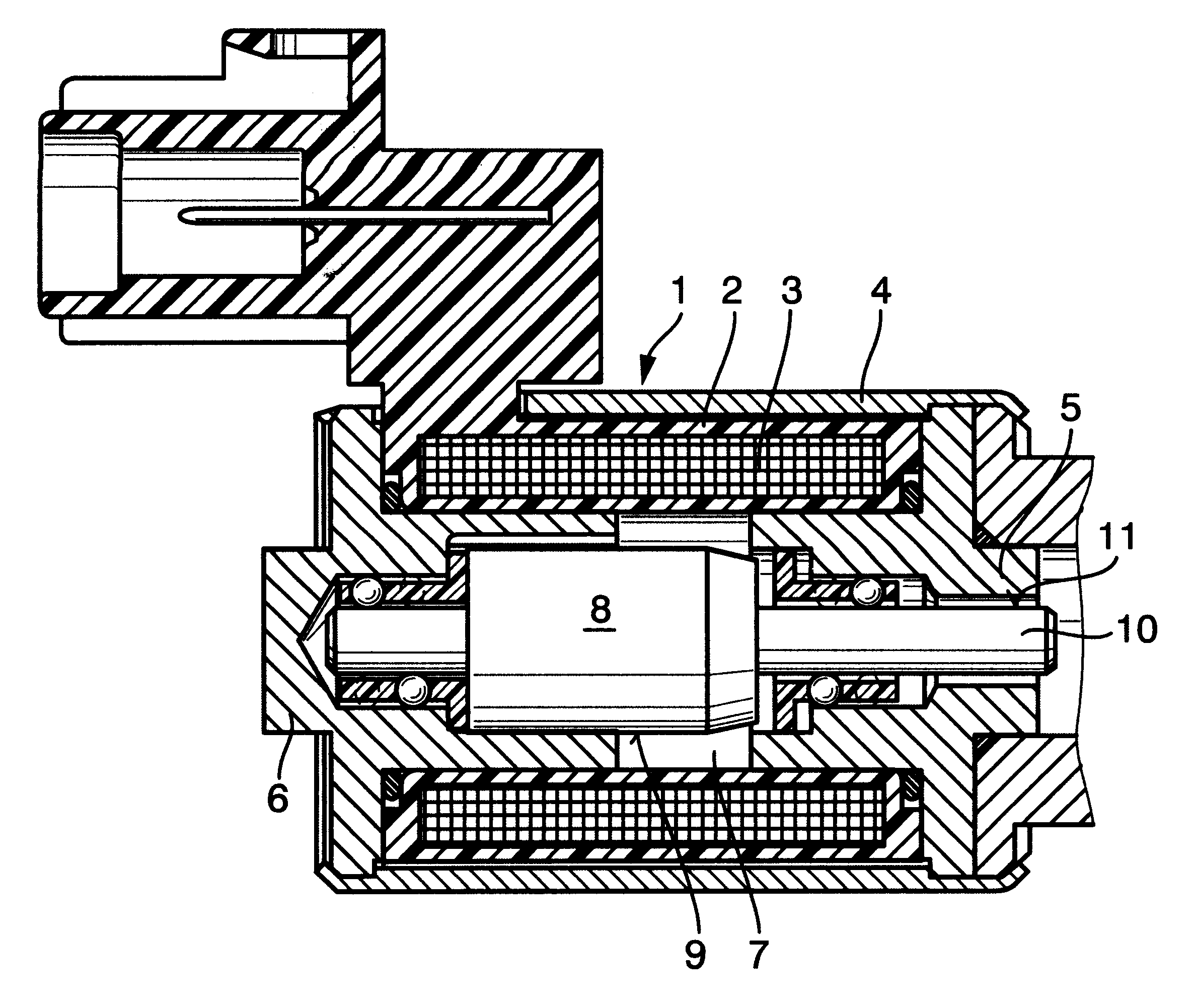
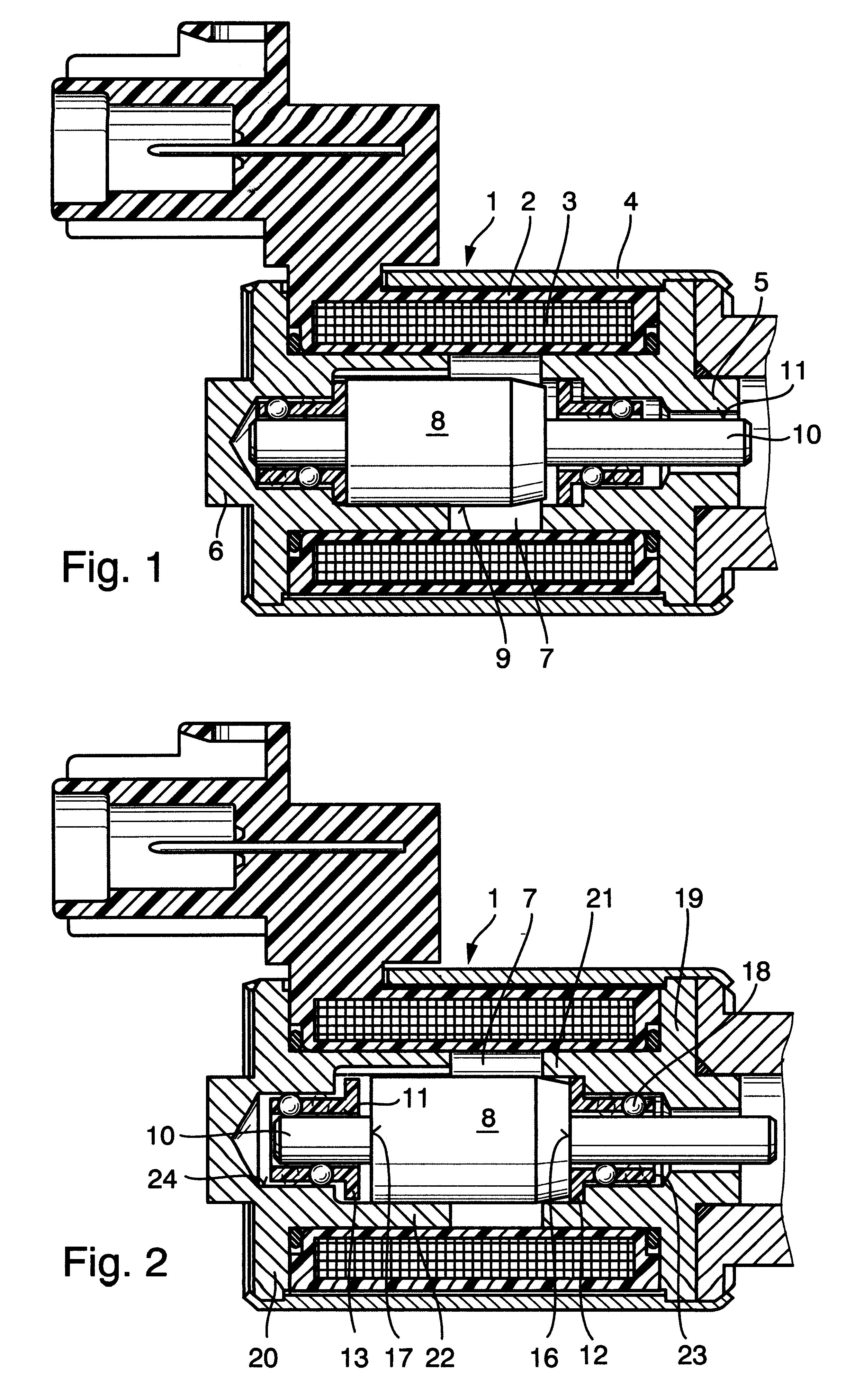
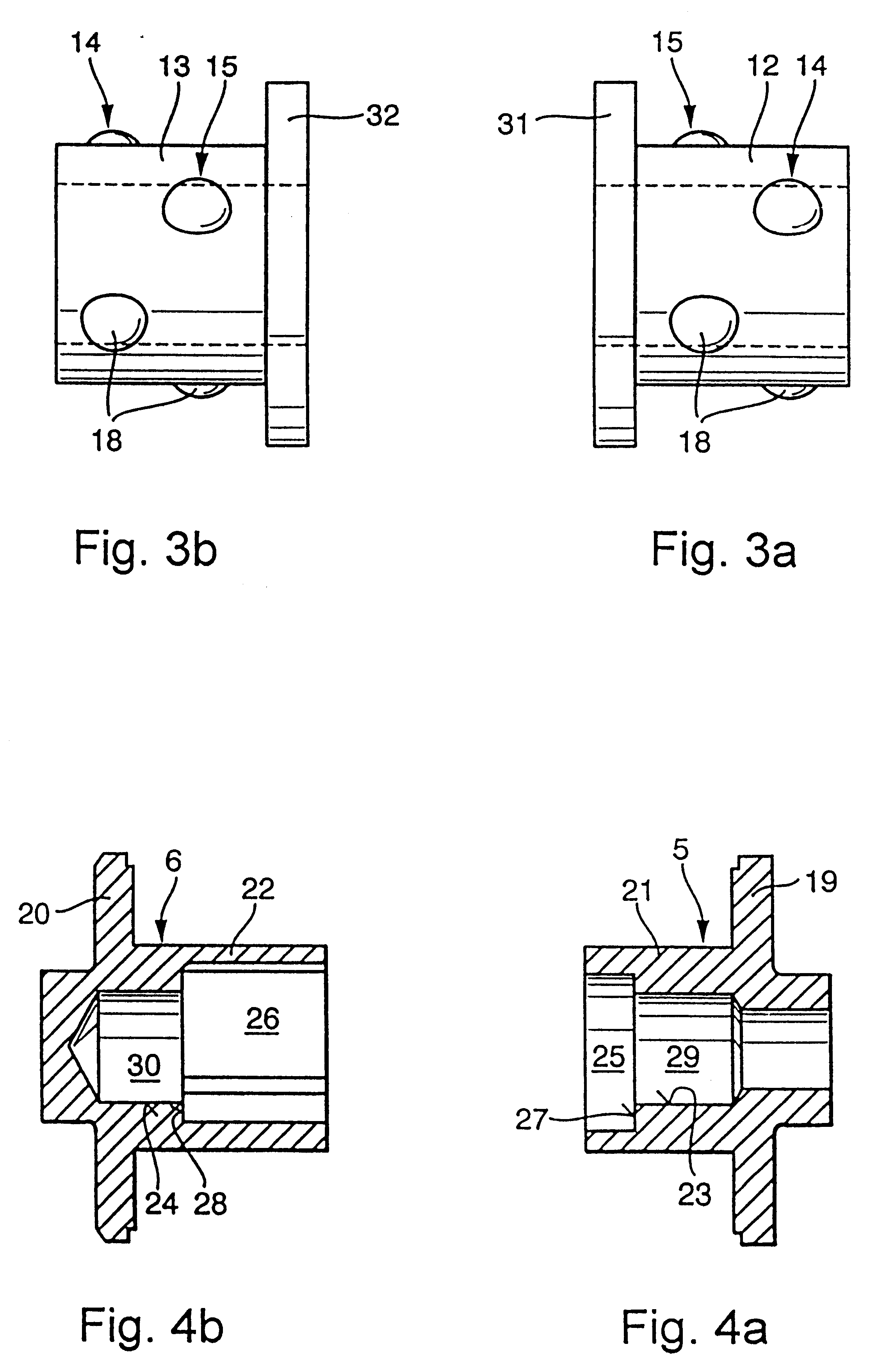
It can be seen from FIG. 4 that each pole shoe 5, 6 of the electromagnet 1 is made up of a pole plate 19, 20 and a hollow cylindrical pole core 21, 22, and that the pole cores 21, 22 extend away from the respective pole plate 19, 20 into the reception 7 of the coil spool 2. The pole cores 21, 22 comprise larger hollow cylinders 25, 26 which receive the end portions of the armature 8, and smaller hollow cylinders 29, 30 whose inner peripheral surfaces 23, 24 form the outer running tracks for the balls 18 of the linear ball cages 12, 13. Besides this, the larger hollow cylinders 25, 26 of the pole cores 21, 22 comprise stepped transitions 27, 28 to the smaller hollow cylinders 29, 30 of the pole cores 21, 22, which transitions are configured as axial stroke limiters of the armature 8. As shown in FIG. 3, an annular collar 31, 32 configured as an anti-stick means of the armature 8 is formed on the armature-proximate end face of each linear ball cage 12, 13 between the end faces 16, 17 ...

second embodiment

As a further difference of the second embodiment from the first, it can be seen in FIGS. 5 to 7 that the one pole shoe 5 of the electromagnet 1 comprises a pole plate 19 and a hollow cylindrical pole core 21 which extends axially away therefrom into the reception 7 of the coil spool 2, while the other pole shoe 6 is formed only by an annular pole plate 20. A non-ferromagnetic pressure pipe 40 lining the entire reception 7 of the coil spool 2 is inserted through this pole plate 20. The inner peripheral surface 41 of this pressure pipe 40 whose strength is increased by additional surface nitriding serves as the outer running track of the balls 36 of the linear ball cage 33 and, where applicable, as the outer sliding surface for the sliding bearing portion 39 of the linear ball cage 38.

It can be seen further in FIGS. 5 to 7 that the reduced-diameter portion 37 of the armature 8 which forms a circumferential shoulder 42 has a larger axial dimension than the linear ball cage 33 or 38, an...

third embodiment

The third embodiment of the electromagnet 1 of the invention shown in FIGS. 8 to 10 has generally the same basic structure as the second embodiment but differs therefrom in that the rotary, longitudinally moveable axial guides of the armature 8 are two plastic bushing-less ball cage strips 46, 47 each of which comprises two spaced apart balls 48, 49 and does not fulfil the simultaneous function of an anti-stick means of the armature 8. As can be seen clearly in FIG. 10, these ball cage strips 46, 47 are arranged within radially opposite axial grooves 50, 51 in the outer peripheral surface 52 of the armature 8, and the bottom surface 53, 54 of each axial groove 50, 51 serves as an inner running track of the balls 48, 49. The outer running track of the balls 48, 49 of the ball cage strips 46, 47 is again formed by the surface-treated inner peripheral surface 59 of a pressure pipe 58 lining the entire reception 7 of the coil spool 2. Identical to the second embodiment, the one pole sho...


PUM


Abstract

An electromagnet (1), particularly a proportional magnet for operating a hydraulic valve, said electromagnet (1) comprising at least one coil winding (3) carried by a hollow cylindrical coil spool (2) which is circumferentially surrounded by a hollow cylindrical magnet housing (4) and limited at each end by a pole shoe (5, 6), said electromagnet (1) further comprising an axially moveable cylindrical armature (8) which is arranged in a hollow cylinder of the coil spool (2) that is configured as an armature space (7), the armature (8) being mounted for low friction in rotary, longitudinally moveable axial guides, and electromagnetically produced axial movements of the armature (8) can be transmitted to a hydraulic valve piston via a push rod (10) which is connected to the armature (8) to form an axial extension thereof. According to the invention, the rotary, longitudinally moveable axial guides of the armature (8) comprise at least one bushing-less linear ball bearing having a number of circumferentially spaced balls while being configured at the same time as an anti-stick means of the armature. The outer peripheral surface (9) of the armature (8) and/or the outer peripheral surface (11) of the push rod (10) is configured as an inner running track for the balls, and the inner peripheral surface of one or more components which limit the armature space (7) of the coil spool (2) forms an outer running track for the balls.

Description

The invention concerns an electromagnet, particularly a proportional magnet for operating a hydraulic valve which is installed within a hydraulic system of a device for varying valve timing in an internal combustion engine, said electromagnet comprising at least one coil winding carried by a hollow cylindrical coil spool which is circumferentially surrounded by a hollow cylindrical magnet housing and limited at each end by a pole shoe, said electromagnet further comprising an axially moveable cylindrical armature which is arranged in a hollow cylinder of the coil spool that is configured as an armature space, the armature being mounted for low friction in rotary, longitudinally moveable axial guides, and electromagnetically produced axial movements of the armature can transmitted to a hydraulic valve piston against the force of a spring via a push rod which is connected to the armature to form an axial extension thereof.A generic proportional or adjusting magnet of the pre-cited typ...

Claims


Application Information

Patent Timeline
IPC IPC(8): H01F7/08H01F7/17
CPCH01F7/17
Inventor GOLOVATAI-SCHMIDT, EDUARDSTEIGERWALD, MARTINSCHAFER, JENS
Owner INA WALZLAGER SCHAEFFLER KG
Why Eureka
Try Eureka