Solid state fluorine sensor system and method

Inactive Publication Date: 2001-11-27
RADIAN INT
View PDF6 Cites 184 Cited by
  • Summary
  • Abstract
  • Description
  • Claims
  • Application Information

AI Technical Summary

Problems solved by technology

These approaches have proven to be extremely effective in PFC reduction, but introduce an ancillary challenge, namely the characterization and abatement of molecular fluorine (F.sub.2).
Concerns include the emission of HF or other regulated toxic compounds into the air, as well as di

Method used


Image

  • Solid state fluorine sensor system and method
  • Solid state fluorine sensor system and method
  • Solid state fluorine sensor system and method

Examples


Embodiment Construction

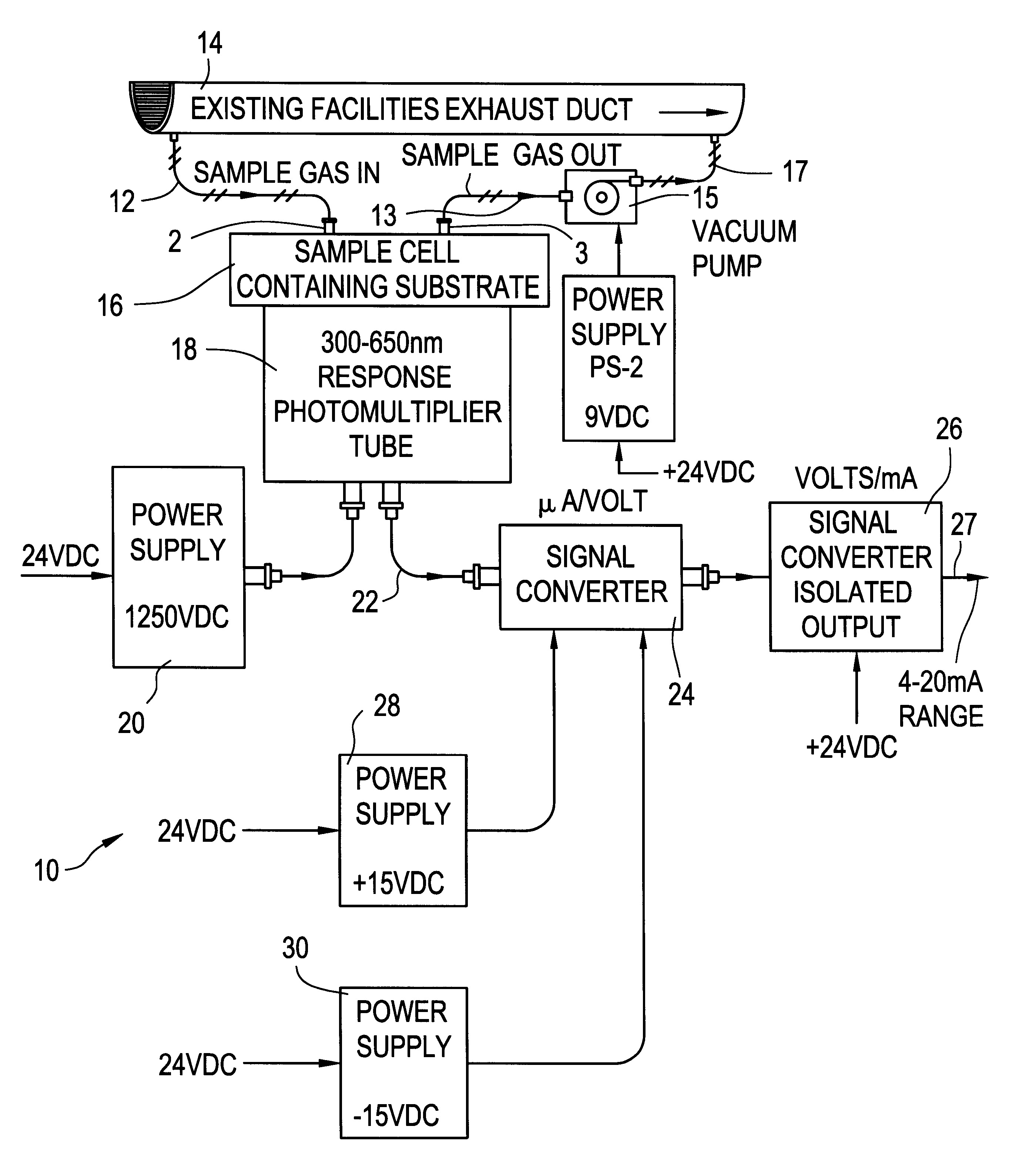
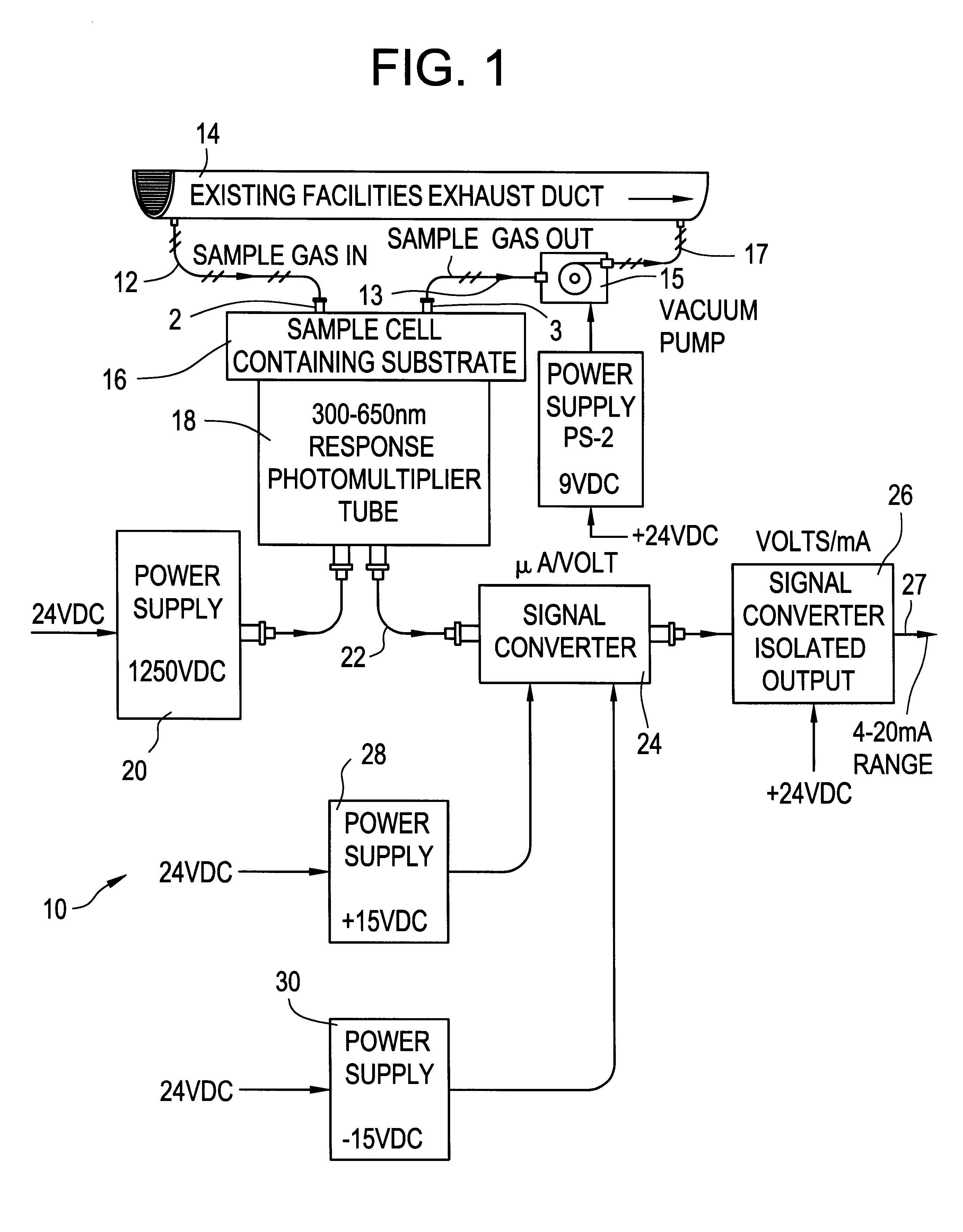
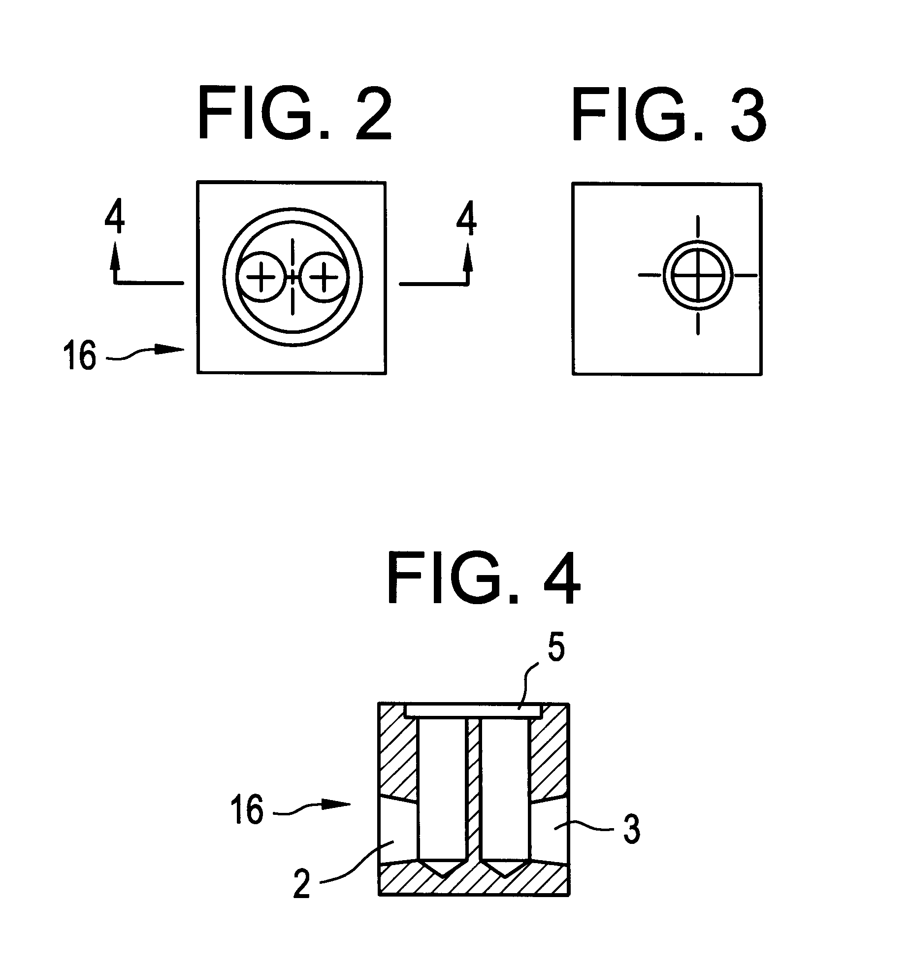
In FIG. 1, a schematic block diagram appears of a fluorine sensor system 10 that allows for the continuous, real-time detection of F.sub.2 in gaseous streams. System 10 can be applied as either an in-situ or extractive exhaust stream monitoring device. The extractive configuration depicted in the FIG. 1 illustrates how a slipstream 12 may be drawn from an exhaust duct 14 through a small sample cell 16 via cell inlet 2 at moderate (<5 slpm) flow. FIGS. 2, 3 and 4 depicting the cell 16, may be considered simultaneously with this description. The sample gas is moved through the cell 16 by a vacuum pump 15 which draws the gas from cell 16 via an outlet 3 and line 13 and returns the gas to duct 14 via line 17. The cell 16 is designed such that the sample gas will uniformly interact with a sodium salicylate substrate deposited on a window, typical dimensions of which can e.g., be 25 mm diameter.times.2 mm thick. The cell is made of a machined block of aluminum, which is nickel plated to m...


PUM


Abstract

A gaseous fluorine detection system is provided which includes a generally enclosed sample cell containing a substrate comprising a material which interacts with fluorine gas to generate radiant energy. A gas sample of fluorine, the concentration levels of which are to be evaluated is flowed through the cell. A photomultiplier tube is positioned to receive the resulting radiant energy and generate an electrical output signal related to the level of said radiant energy. Means are provided for measuring the said photomultiplier output signal and relating same to the fluorine concentration of the gas sample provided to the cell.

Description

This invention relates generally to analytic methods and apparatus, and more specifically relates to a system for use in carrying out measurements of gas samples extracted from semiconductor tool exhausts, or derived from other environments of interest. The invention is also applicable to process control applications related to general chemical process environments.BACKGROUND OF INVENTIONChemical emissions from the manufacturing processes used in the semiconductor industry represent serious occupational and environmental hazards and as such are closely regulated.The use and associated emissions of perfluorocompounds (PFCs) as suspected greenhouse gases within the semiconductor industry have indeed received increased attention in recent years. The 1997 Kyoto Protocol provided the impetus for major industries to address global warming issues, and the semiconductor industry has taken a proactive response toward PFC emissions reduction. The World Semiconductor Council (WSC), comprised o...

Claims


Application Information

Patent Timeline
IPC IPC(8): G01N21/03G01N21/77G01N21/05G01N21/76
CPCG01N21/05G01N21/76G01N21/77
Inventor LAUSH, CURTIS T.
Owner RADIAN INT
Why Eureka
Try Eureka