Oxidation-resistant interfacial coating for fiber-reinforced ceramic

a fiber reinforced ceramic and interfacial coating technology, applied in the direction of yarn, transportation and packaging, chemistry apparatus and processes, etc., can solve the problems of matrix cracking, limited use of cfccs with carbon or boron nitride interfacial coating, and not solving the problem of all

Inactive Publication Date: 2001-11-27
THE UNITED STATES AS REPRESENTED BY THE DEPARTMENT OF ENERGY
View PDF2 Cites 38 Cited by
  • Summary
  • Abstract
  • Description
  • Claims
  • Application Information

AI Technical Summary

Benefits of technology

It is an object of the present invention to provide a multifunctional and multilayered interfacial coating for a ceramic composite wherein the material selected for the interfacial coating remains stable with both the fiber and the matrix of the composite at high temperature and for the life of the component.
Representative compounds for the central layer include, but are not limited to, compounds of silica (SiO.sub.2), alumina (Al.sub.2 O.sub.3), zirconia (ZrO.sub.2), yttria (Y.sub.2 O.sub.3), hafnia (HfO.sub.2), and / or combinations of the above compounds, such as, for example, mullite. In a preferred embodiment of the present invention, significant material mismatch between the layers is achieved for purposes of promoting preferential crack deflection and debonding of the multilayer interfaces as well providing good thermochemical stability at high temperatures if layer 6 is amorphous SiO.sub.2, layer 8 is monoclinic ZrO.sub.2 and layer 10 is amorphous SiO.sub.2.

Problems solved by technology

However, the use of CFCCs with carbon or boron nitride interfacial coatings is limited because in many applications, such as in PFBCs, the CFCCs must remain stable in an oxidizing environment at elevated temperatures, and neither carbon nor boron nitride meet this requirement.
Although it is widely accepted that non-oxide CFCCs will not be used in designs that would subject the component to stresses larger than the so-called matrix cracking stress, accidental stress excursions beyond this stress invariably will occur and result in matrix cracking.
Still other approaches that have been used to extend the service life of CFCCs consist in using low-viscosity outer protective coatings or matrix additives to heal matrix cracks, and while some of these concepts might alleviate the lack of environmental stability of the fiber / matrix interface, they do not altogether solve it.
Furthermore, matrix crack healing may be undesirable in filtration applications since it would be detrimental for the permeability characteristics of the filter material.

Method used


Image

  • Oxidation-resistant interfacial coating for fiber-reinforced ceramic
  • Oxidation-resistant interfacial coating for fiber-reinforced ceramic

Examples


Embodiment Construction

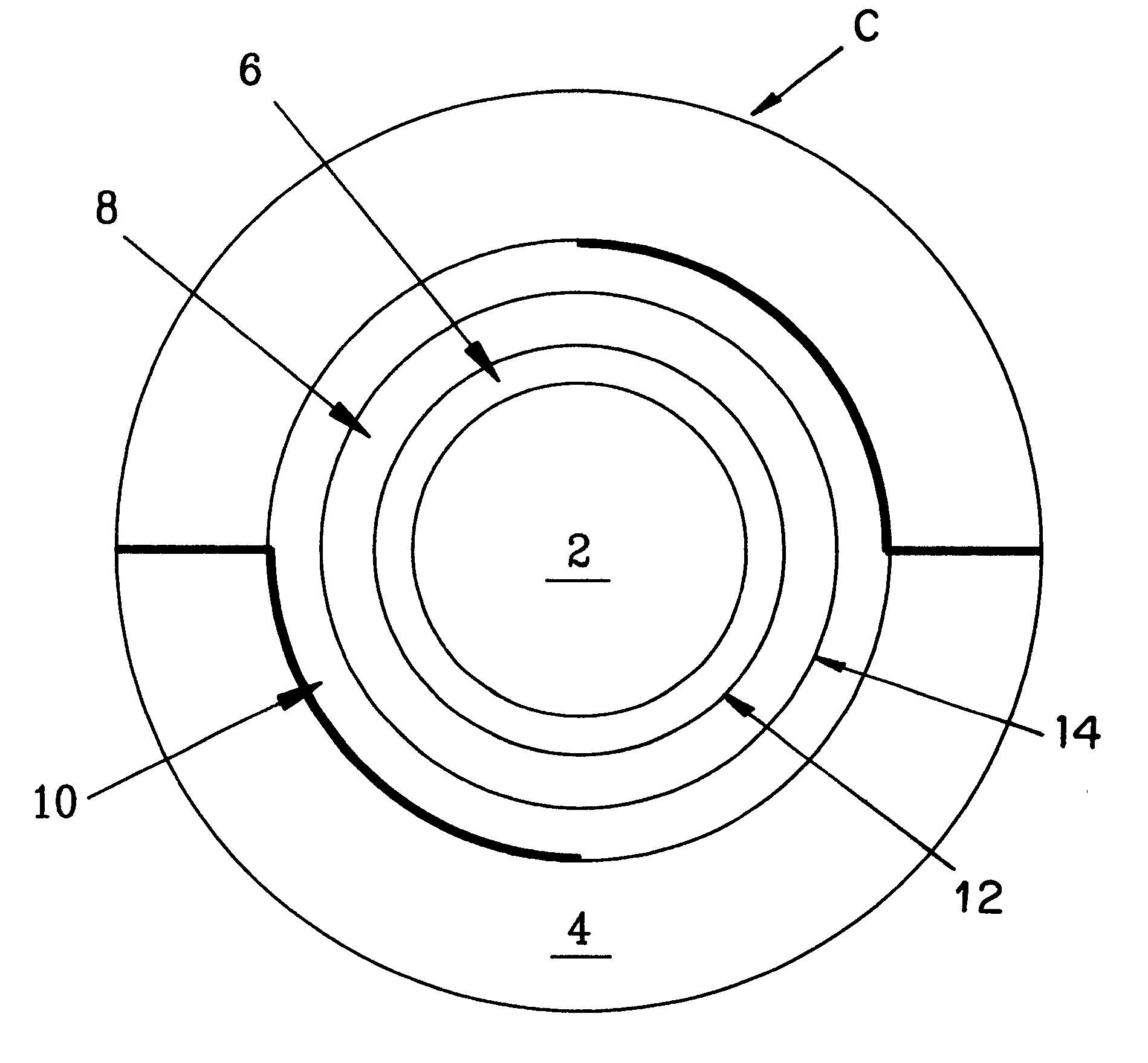
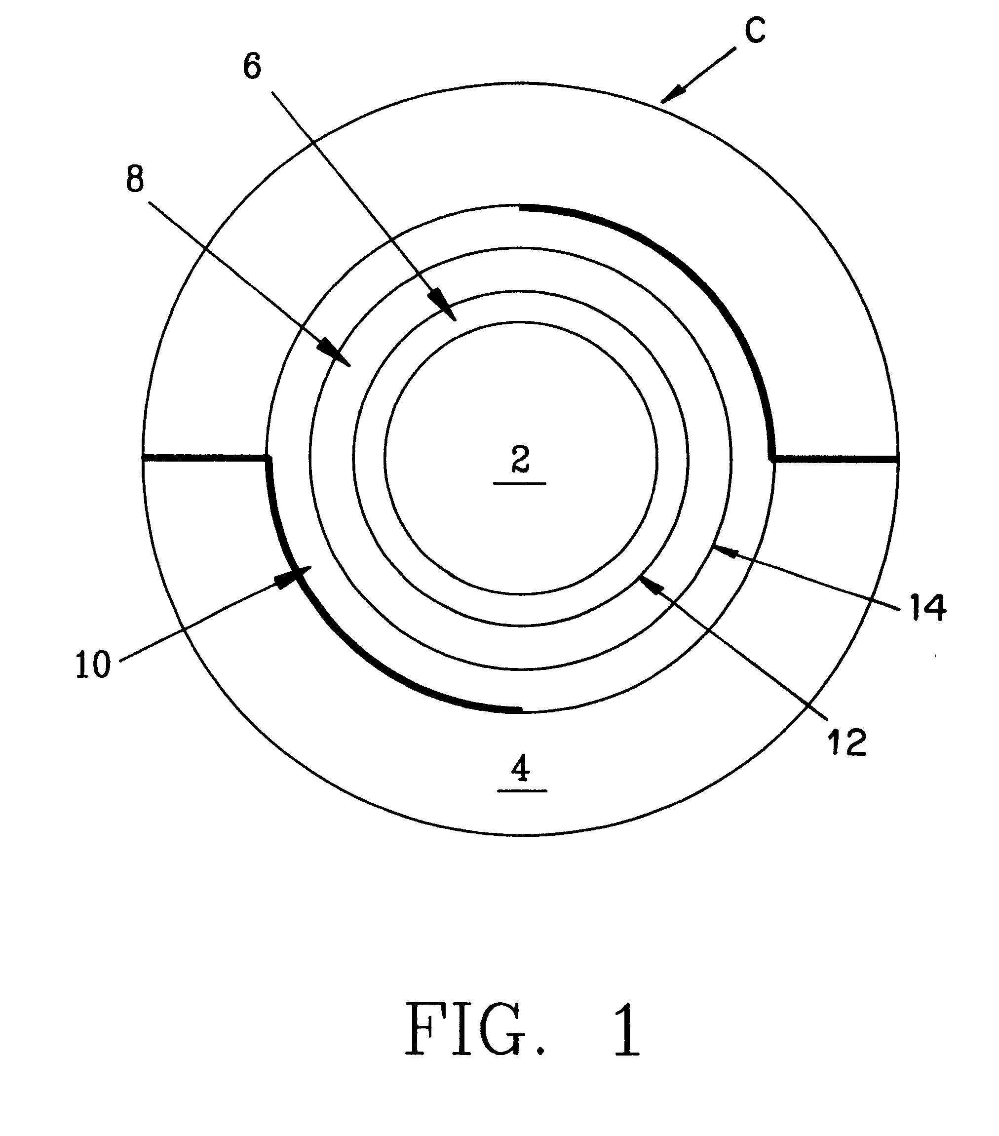
SiC / SiC minicomposites were prepared and provided with three separate oxide interface layers utilizing significant material mismatch of thermoelastic properties between adjacent layers so as to provide preferential crack deflection and debonding of the multilayer interfaces between the layers. The present example is described in J. Am. Ceram. Soc., 81 [3] 717-20 (1998), which is incorporated herein by reference.

In this example, SiO.sub.2 / ZrO.sub.2 / SiO.sub.2 was selected for the multilayer interphase and infiltrated into a SiC fiber tow (Hi-Nicalon.TM., Nippon Carbon, Japan) using a small hot-wall chemical vapor deposition (CVD) reactor by gas switching from SiCl.sub.4 to ZrCl.sub.4 to SiCl.sub.4 with CO.sub.2 and H.sub.2 as a source of oxygen. The reactor was operated at a temperature of 1050.degree. C. and a pressure of 10 kPa. The main features of the CVD reactor are described in M. A. Borst, W. Y. Lee, Y. Zhang, and P. K. Liaw., "Preparation and Characterization of Chemically V...


PUM

PropertyMeasurementUnit
temperatureaaaaaaaaaa
diameteraaaaaaaaaa
diameteraaaaaaaaaa

Abstract

A ceramic-matrix composite having a multilayered interfacial coating adapted to protect the reinforcing fibers from long-term oxidation, while allowing these to bridge the wake of advancing cracks in the matrix, is provided by selectively mismatching materials within adjacent layers of the interfacial coating, the materials having different coefficients of thermal expansion so that a low toughness interface region is created to promote crack deflection either within an interior layer of the mismatched interfacial coating or between adjacent layers of the mismatched interfacial coating.

Description

The present invention relates to fiber reinforced ceramic composites and more specifically to interfacial coatings for such composites.The U.S. government has a paid-up license in this invention and the right in limited circumstances to require the patent owner to license others on reasonable terms as provided for under the terms of Department of Energy contract number DE-AC05-96OR22464.Over the last twenty years, the development of continuous fiber-reinforced ceramics (CFCCs) has been driven, to a large extent, by the promise of substantial economic and environmental benefits if these materials are used in advanced industrial applications. M. A. Karnitz, D. F. Craig and S. L. Richlen, "Continuous Fiber Ceramic Composites Program," Am. Ceram. Soc. Bull., 70, 3 (1991) pp. 430-5.Except for a few applications at "low temperature" when ceramics may offer superior chemical, wear, or electrical properties over conventional materials, the main attraction for using ceramic materials in indu...

Claims


Application Information

Patent Timeline
Patent Type & Authority Patents(United States)
IPC IPC(8): C04B35/80C04B35/565
CPCC04B35/565C04B35/806Y10T428/2949Y10T428/2942Y10T428/2958Y10T428/2938C04B35/80
Inventor LARA-CURZIO, EDGARMORE, KARREN L.LEE, WOO Y.
Owner THE UNITED STATES AS REPRESENTED BY THE DEPARTMENT OF ENERGY
Why Eureka
Try Eureka