This gives rise to relatively long focal lengths or small viewing apertures, otherwise
spherical aberration will occur causing the graticule image to become blurred and
parallax errors to become large.
This requirement causes the optical arrangement to become long compared to its aperture, and it is difficult to make compact designs.
It is possible to avoid the problem of
spherical aberration by using aspherical lens sets, but these have been difficult and expensive to produce.
Battery life is a fundamental problem when these systems are considered for use in arduous conditions such as military or law
enforcement applications.
Even high performance types of LED have
high current consumptions when maximum brightness is required in bright sunlit conditions.
Reducing the brightness of the LED would enhance the battery life but to the detriment of useability.
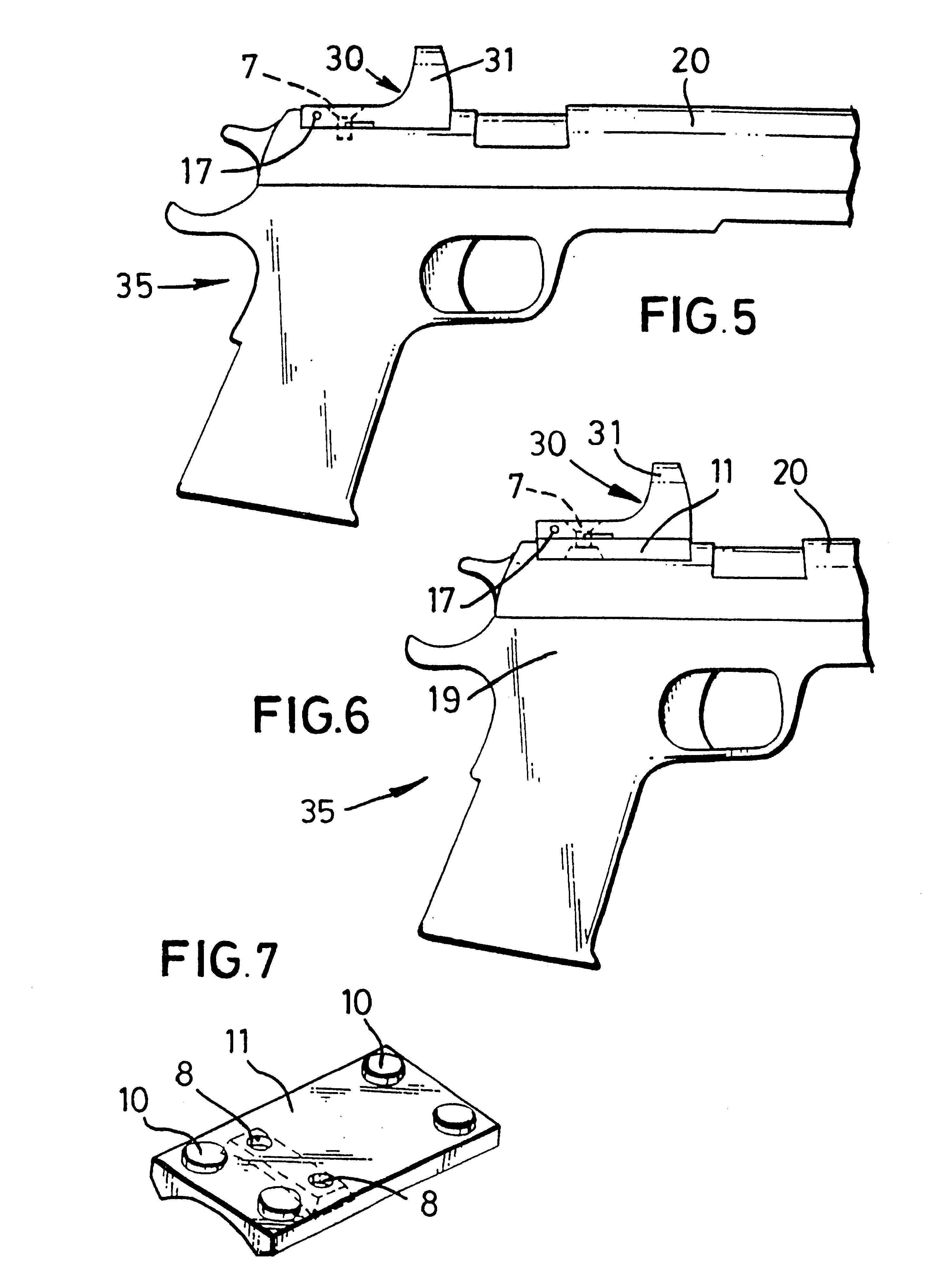
In effect the conventional shape is entirely wrong for mounting onto a hand gun, where a wide aperture is desirable close to the top of the gun.
Any increase in profile causes the gun to become more cumbersome, especially if the
sight weights several once, (1 oz..apprxeq.28 gm).
It also has the
disadvantage that the top of the gun, which can be used by the eye to quickly align the gun with the target, can no longer be seen by the shooter.
A further
disadvantage of such a
system is that the gun has to be specifically modified to accept the mounting bracket.
This means that retro-fitting to a standard gun is expensive, and the gun is permanently marred if the
sight is subsequently removed.
Furthermore, most integral
mount systems are specific to one type of hand gun and cannot be fitted to rifles and / or revolvers and / or semi-auto pistols without further specialised brackets.
Most electro-optical sights suffer from the violent vibration and shock that is produced by hand guns when they are fired.
However, the vibration and
high acceleration would then be passed directly to the sight.
Known sights are not constructed in a manner which could be suitably adapted to this type of mounting on the gun's slide or could withstand the forces imposed on it.
Usually, in known sight designs, some or all of these components are mounted permanently within the sight, which means that the sight has to be replaced or repaired by the manufacturer, should failure occur.
Using a switch
system has several disadvantages; primarily the user may
neglect or not have time to actuate the switch and adjust, e.g. for
light intensity, the device when required, or may
neglect to switch the
system off.
If left switched on, on full brightness, the battery will be exhausted in a few hours and the system becomes useless.
Switches also are prone to failure due to vibration, shock and physical damage.
Known systems cannot fulfil this criteria of compactness and ruggedness.
However, the long
focal length makes the overall length of the sight too long for weapons requiring a
short length for the sight, and also seems likely to produce an
aperture ratio no better than about f.3 or f.4.
However, due to its thinness, such a
thin lens would be liable to relaxation and / or movement in use and provide for inaccurate focussing and / or imaging aberrations of the electro-optical sight incorporating such a lens.

