These stresses are even greater on wing structures of amphibious aircraft during water landings because the shock-absorbing devices that are integrated into the
landing gear are not available when landing on water.
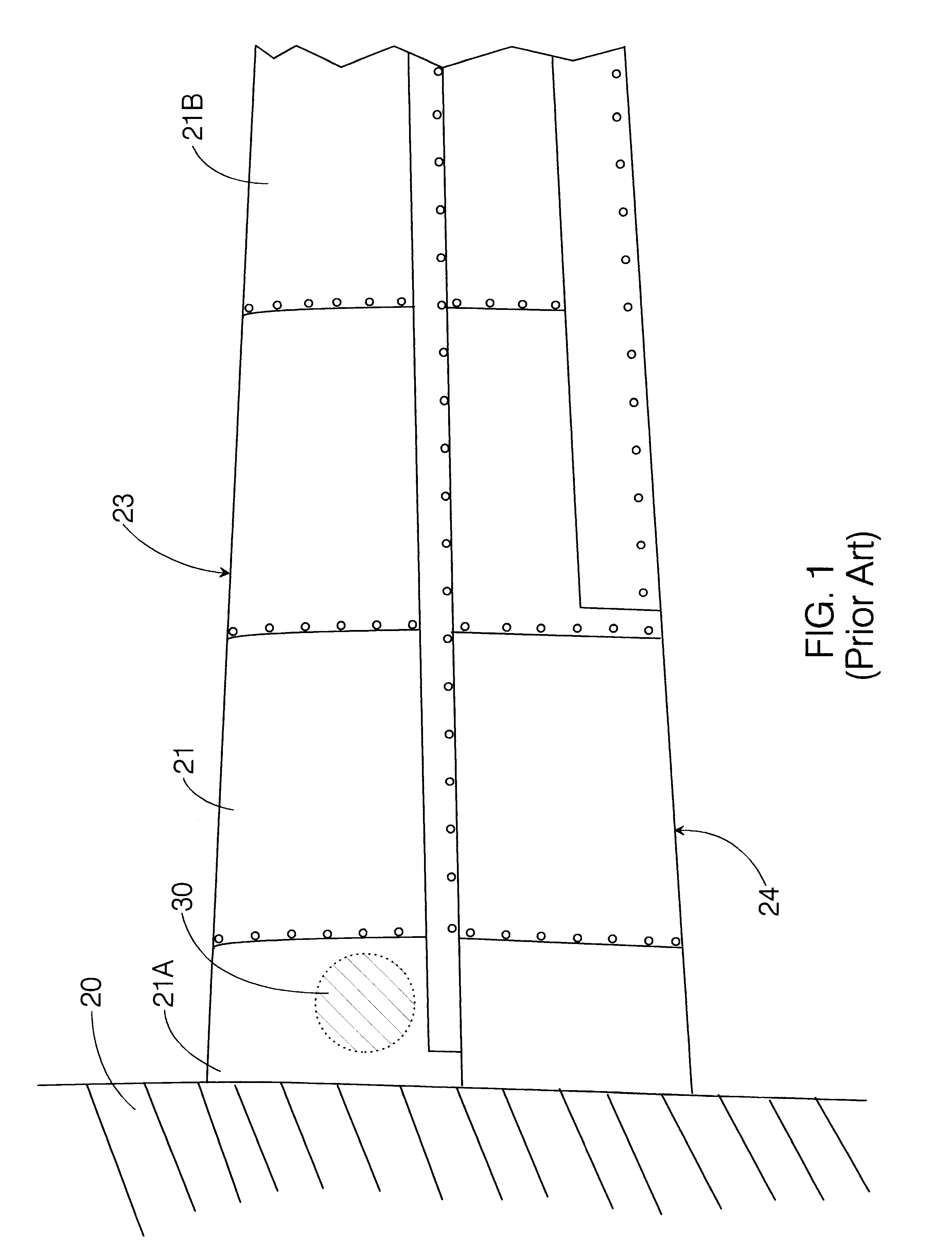
It has been determined that the method of wing spar attachment used in certain Lake amphibious aircraft models may result in cracks in the wing spar, specifically, in the wing spar cap and wing spar attachment bolt-holes.
The wing spar serves to attach the wing to the aircraft
fuselage and these cracks have the potential to cause separation of the wing from the
fuselage during flight, with obvious deleterious consequences.
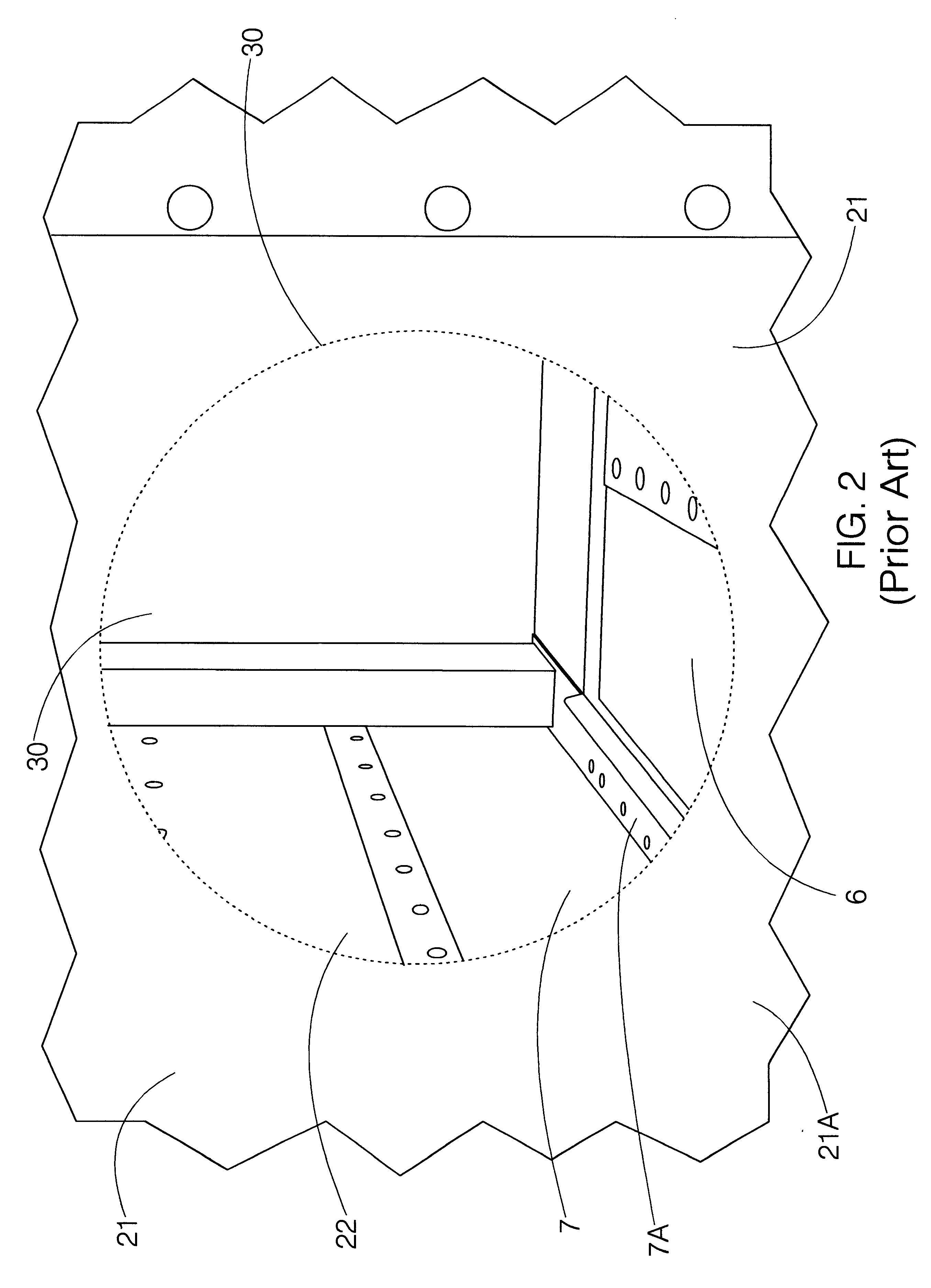
The particular problem to be solved was the
elimination of the structural deficiencies of the wing attachment due to cracks initiating at a machined notch at the
flange termination point of the wing-spar cap angle.
This solution is, however, very costly and time-consuming--it being a very labor-intensive and time-consuming task to replace parts of the wing spar, with a typical cost of $40,000.
Although both of these doubler inventions serve to strengthen aircraft elements, neither provides a solution to the specific problem at hand, which is not as straightforward as slapping more
metal on the spar.
For example, a doubler-strap that is too rigid or has greater strength than the underlying element may itself cause stresses on the element and introduce additional sources of
cracking and structural
weakness.
Conversely, a doubler-strap that is too flexible or has less strength than the underlying element will not provide the additional strength and reinforcement that is required.
Without access to comprehensive
engineering data on the components to be strengthened and on its related flight elements, it can be very difficult to determine the proper strength characteristics required in a doubler without having to carry out a lengthy testing process that may also include destructive tests and, consequently, be very costly because of the material costs.
A further difficulty in constructing a doubler-strap modification kit to solve the particular problem at hand is that there are a number of different aircraft models with wing spars that required strengthening, with dimensions of the area requiring strengthening varying with model, and to a lesser extent any individual plans of a particular model.
Another factor that must be taken into account in developing a doubler as a means of structural reinforcement of a wing spar is the problem of
corrosion.
This becomes a critical issue with amphibious planes, the wings of which may be expected to be regularly exposed to
salt water to a degree not found in the non-amphibious planes that make up the vast majority of the world's aircraft.
Finally, as a safety issue, as well as an economic issue, the doubler reinforcement must be simple to install.
Direct contact between the aluminum filler-strap and the steel doubler-strap, however, introduces the risk of
corrosion on these two parts, thereby exacerbating concerns of prolonged
structural integrity.
Furthermore, the aluminum filler-strap, which is more easily replaceable than the doubler-strap, will corrode before the doubler-strap.
Direct contact between the aluminum filler-strap and the steel doubler-strap, however, introduces the risk of corrosion on these two parts, thereby exacerbating concerns of prolonged
structural integrity.
Furthermore, the aluminum filler-strap, which is more easily replaceable than the doubler-strap, will corrode before the doubler-strap.
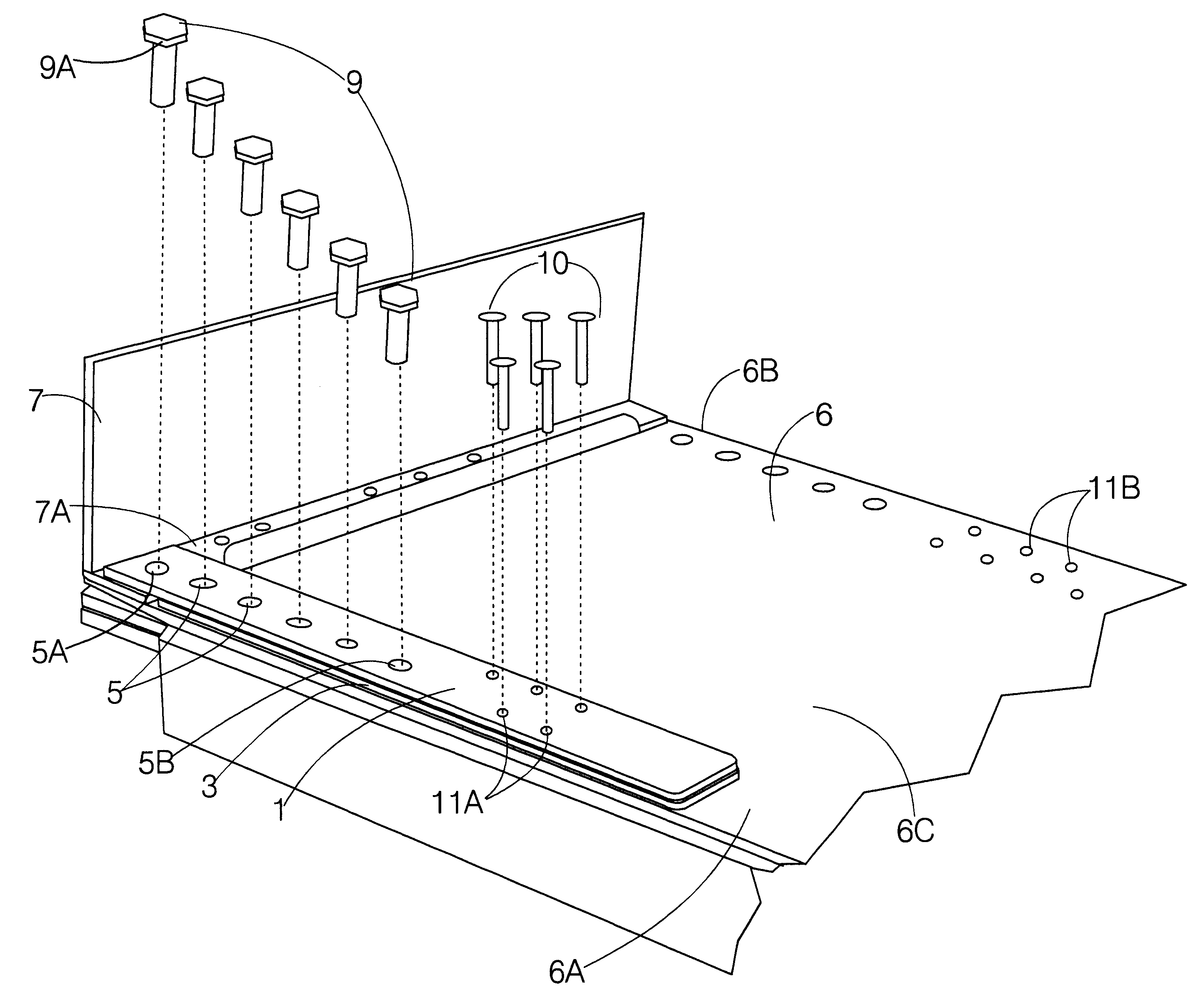
A main difficulty was determining the proper dimensions to ensure a single-size doubler would fit all aircraft.
In the course of solving the problem, it was determined that the initial doubler-strap prototype was too short and, although it would have solved the initial
cracking problem on the wing-spar cap angle and would have satisfied the universality condition, was likely to cause additional
cracking on the wing spar web in the area around the first outboard wing-attach bolt-hole.
Further, it was determined that a single rectangular shape was inappropriate, since it was introducing additional and parasitic stresses onto the wing-spar cap angle.
It was discovered that the filler and doubler-straps could be installed incorrectly, resulting in an interference between the doubler-strap and the wing-spar cap angle that was almost impossible to perceive because the intervention is most readily discernible when the straps are being laid in place and ascess to the area for
visual inspection is effectively blocked by the arm of the person installing the parts.
Although the interference was minor, it could have serious effects in the longterm on the airworthiness of the aircraft.

