Polymer electrolyte fuel cell showing stable and outstanding electric-power generating characteristics

a technology of electrolyte fuel cell and polymer electrolyte, which is applied in the direction of electrochemical generators, cell components, cell component details, etc., can solve the problems of fuel gas blocking, fuel gas blocking, fuel membrane needs to be moistened, etc., and achieve the effect of stable generation of electric power over tim

Inactive Publication Date: 2001-12-11
JX NIPPON OIL & ENERGY CORP
View PDF14 Cites 56 Cited by
  • Summary
  • Abstract
  • Description
  • Claims
  • Application Information

AI Technical Summary

Benefits of technology

The present invention provides a polymer electrolyte fuel cell in which an extension path is formed on an anode-side plate and a gas-selectively-exhausting means for selectively exhausting gas is formed in a gas loophole which is formed upstream of the end of the extension path, the gas loophole overlaying the extension path. This construction prevents the fuel gas from being blocked in the channels and supplies the fuel gas to the anode in entirety, resulting in stable generation of electric power over time.

Problems solved by technology

Meanwhile, a problem of such polymer electrolyte fuel cells is that the polymer electrolyte membrane needs to be moistened during operation to maintain the ionic conductivity of the membrane.
However, such methods still have a problem that the fuel gas is blocked when meniscuses of water are formed due to capillary phenomenon at the downstream edge of the anode-side channels where three phases (fuel gas exhaust as gas phase, the channel plate as solid phase, and water as liquid phase) gather together.
FIG. 1 shows the problem that the fuel gas is blocked when meniscuses are formed at the downstream edge of the anode-side channels.
When such meniscuses are formed, the channels are blocked and the fuel gas is unequally supplied to the anode.
However, widening the channels is not preferable since it increases the electrical resistence in the fuel cell.
However, this type of conventional polymer electrolyte fuel cells have a problem that different amounts of water run through a plurality of channels.
In this case, however, a pump with a large capacity is required.
Moreover, the fuel gas supply effeciency decreases since water is excessively supplied to a part of the channels.

Method used


Image

  • Polymer electrolyte fuel cell showing stable and outstanding electric-power generating characteristics
  • Polymer electrolyte fuel cell showing stable and outstanding electric-power generating characteristics
  • Polymer electrolyte fuel cell showing stable and outstanding electric-power generating characteristics

Examples


embodiment 2

The fuel cell of the present embodiment is the same as Embodiment 1 except that water is supplied to all of the anode-side channels 400, and that water is supplied more upstream than the fuel gas.

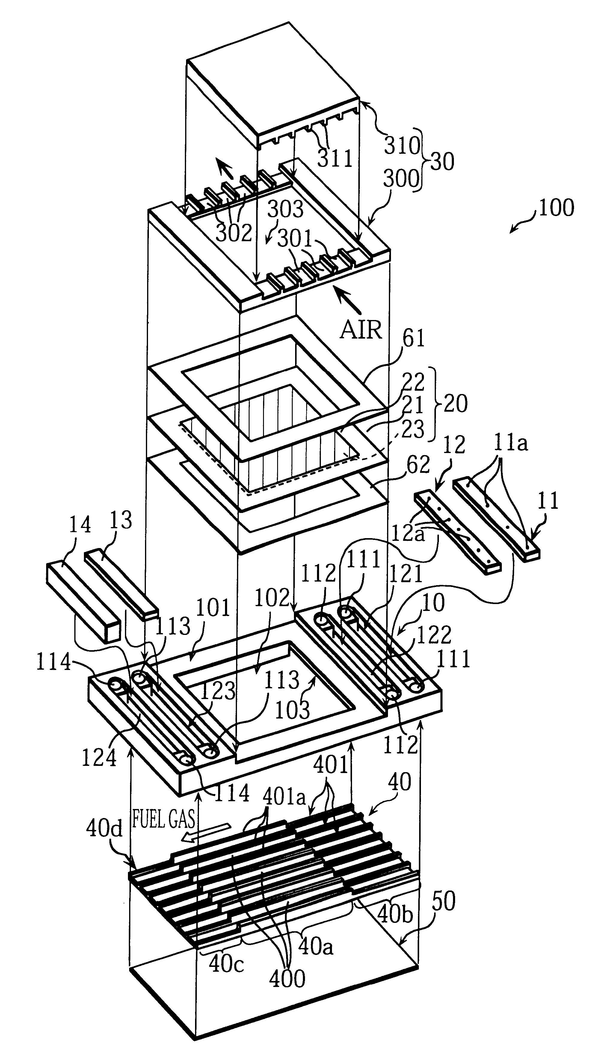
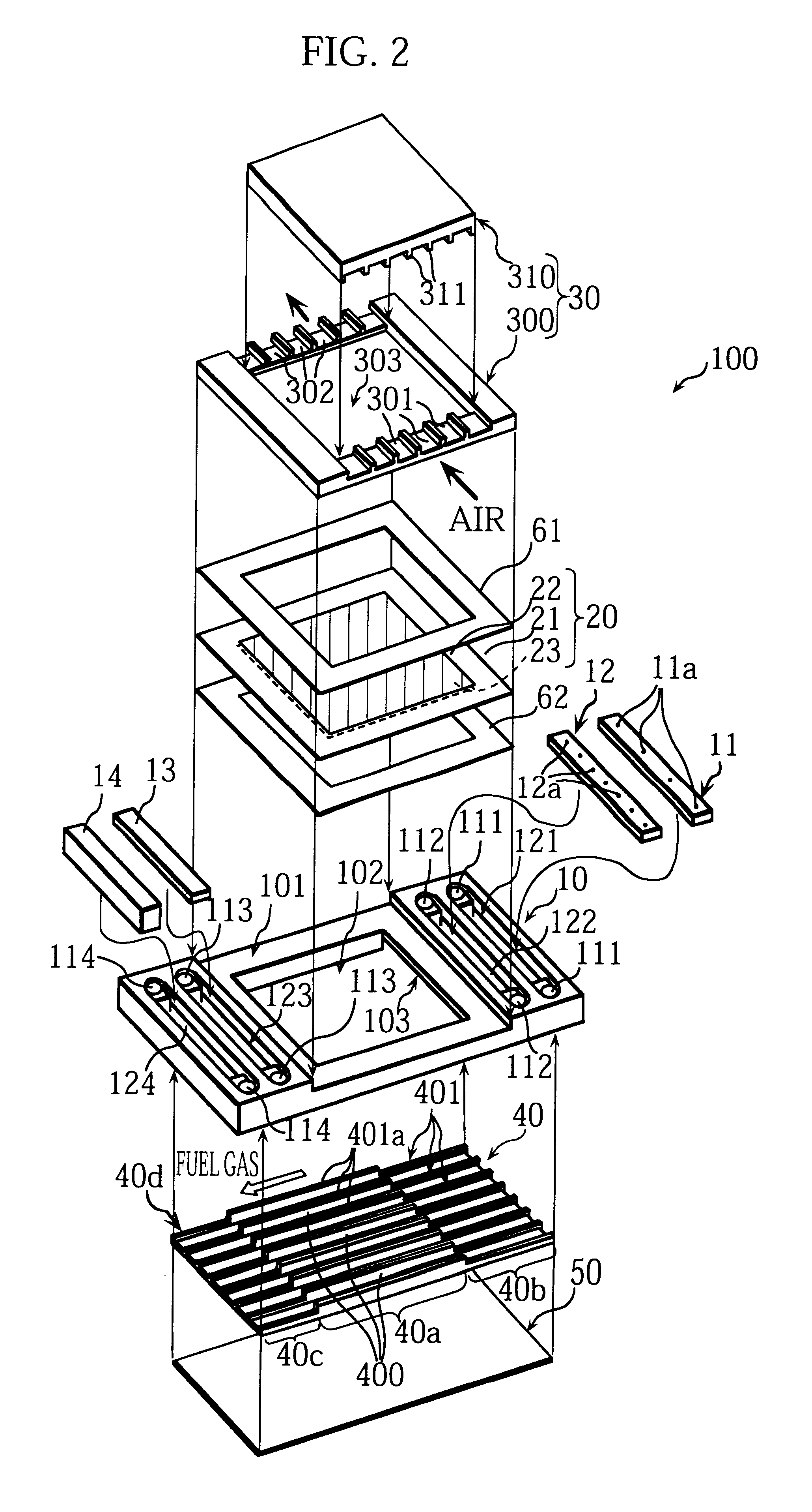
More specifically, in the present embodiment, in the cell unit 100 shown in FIG. 2, the water distribution plate 11 is not fitted in the slot 121. The fuel gas is supplied to the manifolds 111, then distributed to the anode-side channels 400 through the slot 121. A water distribution plate, which is the same as the gas distribution plate 12 with pores corresponding to the anode-side channels 400, is fitted into the slot 122. Water is supplied to the manifolds 112, then distributed to the anode-side channels 400 through the pores.

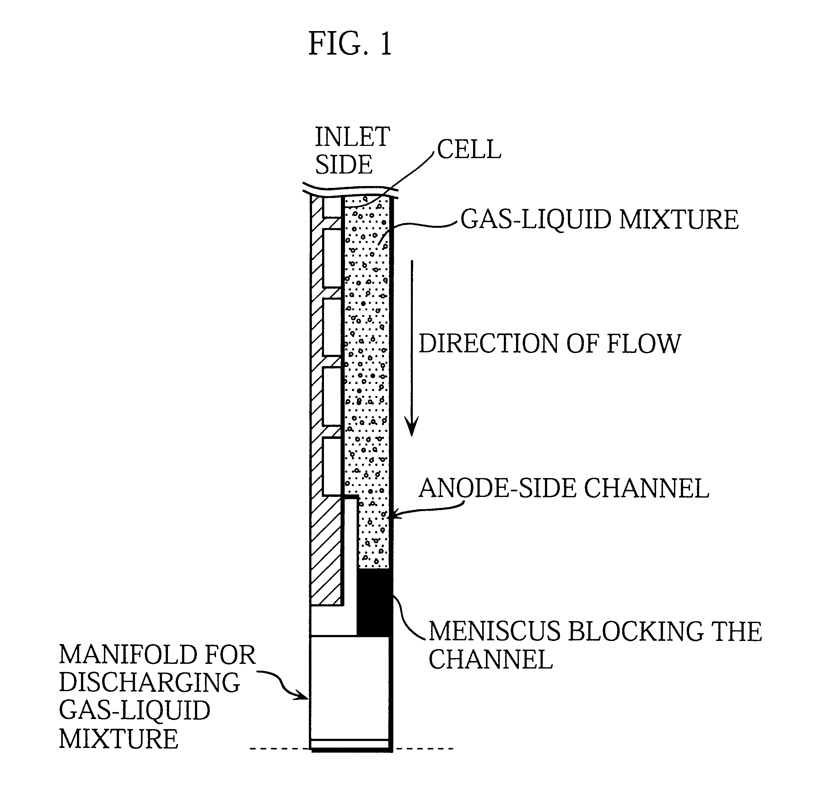
FIG. 8 is a sectional view of the fuel cell of the present embodiment taken along the anode-side channels, and shows the generation, flow, and discharge of the gas-liquid mixture in the channels.

In the present embodiment, the gas-liquid mixture is generated in and f...

embodiment 3

FIG. 9 shows the operation of the fuel cell of the present embodiment, and is, like FIG. 7A, a top plan view of the cell unit.

The fuel cell of the present embodiment is the same as Embodiment 1 except that, as shown in FIG. 9, on the surface of the frame 10, two drain slots 115 are formed. Each drain slot 115 is formed between and connects a manifold 113 for exhausting gas and a manifold 114 for discharging water. A spongy material 116, which is the same as the spongy material 14, is fitted in the drain slot 115 to form a drain path.

During the operation of the fuel cell, especially during the operation with a high fuel utilization factor, the water contained in the gas is sometimes condensed in the manifolds 113 for exhausting gas. However, the water in the manifolds 113 is guided to the manifolds 114 (for discharging water) through the spongy material 116 fitted in the drain slot 115. With this construction, the blockage of the manifolds 113 by the condensed water is avoided.

On the...

embodiment 4

The fuel cell of the present embodiment is the same as Embodiment 2 except that a slit formation plate 15 replaces the gas-permeable plate 13 to selectively exhaust the gas in the gas-liquid mixture.

FIG. 10 is an assembly drawing of a main part of the cell unit which constitutes the fuel cell of the present embodiment. FIG. 11 is a sectional view of the fuel cell taken along the anode-side channels.

As shown in the above drawings, the slit formation plate 15 is a plate bended along the direction of the length. The slit formation plate 15 is divided into two parts: a support part 15a; and a shield part 15b. The slit formation plate 15 is attached along the slot 123.

The slit formation plate 15 is formed so that the support part 15a is held between the anode-side channel substrate 40 and the frame 10, that the shield part 15b shields most of the slot 123, and that a slit 15c is formed between the shield part 15b and the inside of the slot 123 so that gas can pass through the slit 15c.

As...


PUM

PropertyMeasurementUnit
widthaaaaaaaaaa
diameteraaaaaaaaaa
lengthaaaaaaaaaa

Abstract

A solid polymer fuel cell which can stably generate electric power for long, because the cell is enabled to uniformly supply a fuel gas to all anodes by means of extended flow passages which are extended from anode-side flow passages and formed on a anode-side plate on the downstream side of the ends of the anodes in the direction of fuel gas flow, a water absorbing means for nearly uniformly performing water absorption, water retention, and drainage on all channels provided at the ends of the extended flow passages, and a selective gas discharging means for discharging a gas more selectively than water on the upstream side of the water absorbing means. In addition, the power generation characteristics and service life of the fuel cell can be improved further, because the cell can maintain a solid polymer film in a moist state as a whole and can efficiently supply the fuel gas to all anodes by a means for distributing the fuel gas to the inlet sections of the anode-side flow passages and a means for distributing water from a water source to the inlet sections of the anode-side flow passages through holes having a prescribed form and leading to the inlet sections of the anode-side flow passages.

Description

This invention relates to a polymer electrolyte fuel cell, more specifically, to a polymer electrolyte fuel cell in which fuel gas and water are supplied to anode-side channels to generate electric power.Many of commercially practical polymer electrolyte fuel cells are a stack of a plurality of cell units each of which includes a cell sandwiched by a pair of plates in which gas-flow channels are formed, where the cell is composed of an anode, a cathode, and a polymer electrolyte membrane, the polymer electrolyte membrane being disposed between the anode and cathode. The polymer electrolyte fuel cell, when operated, generates electricity through electro-chemical reaction while the cathode-side channels are supplied with air as oxidizer and the anode-side channels are supplied with a fuel gas.Meanwhile, a problem of such polymer electrolyte fuel cells is that the polymer electrolyte membrane needs to be moistened during operation to maintain the ionic conductivity of the membrane. To ...

Claims


Application Information

Patent Timeline
Patent Type & Authority Patents(United States)
IPC IPC(8): H01M8/24H01M8/06H01M8/10H01M8/02H01M8/04
CPCH01M8/0228H01M8/0247H01M8/026H01M8/04089H01M8/04119H01M8/04231H01M8/04291H01M8/0662H01M8/1002H01M8/241H01M8/242H01M8/0271H01M8/04029H01M2300/0082Y02E60/521H01M8/1007Y02E60/50H01M8/2483H01M8/0258
Inventor YASUO, TAKASHINAKAOKA, TORUHAMADA, AKIRAMIYAKE, YASUOYOSHIMOTO, YASUNORIKARAKANE, MITSUO
Owner JX NIPPON OIL & ENERGY CORP
Why Eureka
Try Eureka